Improve 2D HEC-RAS Model Stability
A lot of things can be investigated to improve 2D HEC-RAS model stability. This post covers some of the most critical factors to investigate when a model starts to act unstable. While these tips are a great starting point for troubleshooting, this guide is intended as a practical overview – not a replacement for hydraulic reference manuals or an exhaustive list of every possible stability fix.
1. Fixed Time Step
For fixed time step modeling, the first thing a modeler wants to check is if a time step is chosen appropriately according to Courant Number (C =<1):
Time Step = Cell Size/Wave Celerity (Wave Celerity is about 1.33 ~1.67 x Flow Velocity)
For time step calculation purpose, an initial Wave Celerity can be estimated to be 5ft/s ~ 10ft/s. For example, assume a 2D cell size is 100ft x 100ft, the time step (TS) can calculated as 100/10 sec=10 sec. It is prudent to run a time step sensitivity analysis using 2 x TS and 0.5 x TS in addition to the calculated TS to compare the 2D model performance and results. Since HEC-RAS uses implicit 1D and 2D solvers, a greater Courant Number (C=<2, or 3) may be allowed, which in turn means a larger time step.
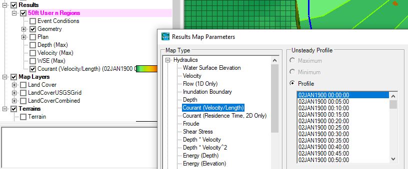
A Courant (Velocity/Length) Results Map in RAS Mapper is helpful to identify cells with high Courant Numbers.
2. Adaptive Time Step – Adjust Time Step Based on Courant Number
The Advanced Time Step Control under the Unsteady Computation Options and Tolerances includes the option for the model to compute appropriate time steps based on Courant Number (Figure 2).

The fixed time step method should be the preferred method in a HEC-RAS 2D model. The adaptive time step method based on Courant Number can be applied when the fixed time step method fails to produce a stable model run, for example, a dam breach analysis using shallow water equations (SWE).
3. Cell, Mesh and Breakline
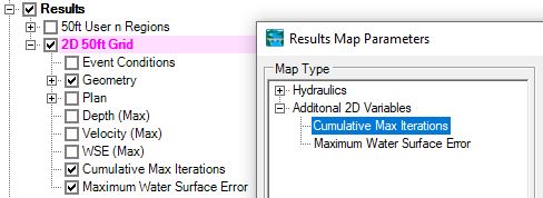
Instabilities often occur where the cell sizes or shapes change abruptly or where the mesh is poorly aligned with the flow. Bad cells or bad meshes often result in excessive iterations or large water surface errors, which can be viewed by turning on the Cumulative Max Iterations and Maximum Water Surface Error results layer (Figure 3).
There are several ways to improve cell and mesh quality.
3.1 Cell Size: Avoid drastic changes in cell size. If you are transitioning from a 50-ft grid to a 10-ft grid, use refinement regions to create a gradual transition.
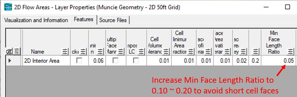
3.2 Cell Shape: HEC-RAS does not like weird shaped cells. To avoid tiny cell faces, increase the default value of Min Face Length Ratio to 0.10 to 0.20. Per HEC-RAS, the Min Face Length Ratio is defined as a percentage of the distance between neighboring computational points.
3.3 Partially Wetted Cell: When only a small portion of the cell is wet (e.g., a corner), the wetted volume is very small and even moderate inflow can produce artificially high velocities. Furthermore, in partially wetted cells (especially on steep or irregular terrain), small changes in WSE cause large relative changes in wetted area/volume, which makes HEC-RAS struggle to find a solution. To reduce partially wetted cells, a modeler can try to
- change cell sizes by testing either larger or smaller cells in the problematic area
- apply breaklines to ensure 2D meshes follows high ground (ridges, top of banks) and low ground (channel inverts)
- align 2D mesh faces with the primary flow direction by enforcing breaklines or refinement regions
4. Downstream Boundary Condition
If possible, always extend the downstream boundary further away from the primary study area to minimize unwanted boundary effects.
The energy slope for a normal depth boundary condition can be estimated as the terrain ground slope at the boundary location. The Measure Tool in Ras Mapper can be used to measure the terrain slope at the boundary location.
5. 2D Connection – Bridge
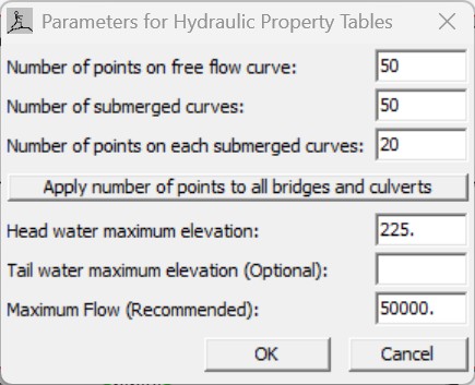
For simplified 2D bridge modeling, it is important to examine the bridge 1D rating curves to make sure they are smooth and having enough resolution to cover the flows and elevations to be modeled by entering appropriate HTab Parameters (Figure 4). Modelers shall focus on the elevations of the rating curves where ineffective areas are turned on/off, or low flow is transitioning to high flow.
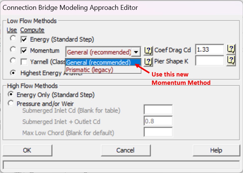
In HEC-RAS 7.0, a new momentum equation called General (Figure 5) is introduced to replace the old one (Prismatic Legacy) for low flow bridge methods. This new momentum equation is able to provide smoother 1D rating curves.
6. 2D Connection – Culvert
It is ideal for a culvert’s inlet and outlet ends to reside in bigger and lower cells. The culvert barrel GIS data tool should be used to align the culvert properly. Sometimes it is also helpful to improve model stability by enlarging the connecting cells of the inlet and outlet of the culvert through manipulating the computation points.
Ensure the culvert inlet and outlet inverts are not lower than the minimum elevations of the connecting cells; otherwise, raise the culvert invert or use RAS Mapper terrain modification tools to lower the connecting cell elevations.
7. Lateral Structure
In HEC-RAS 2D, a lateral structure acts as a “1D bridge” between 2D cells or between a 1D reach and a 2D area. This hybrid approach is powerful but introduces model numerical instability because the 1D and the 2D equations have fundamentally different mathematical foundations. Several ways can be tested to improve lateral structure stability including:
- Determine if weir equation or 2D equation is appropriate for the lateral structure. If you are modeling a structure with a clear crest or if there is a significant “drop” from one side to the other, the weir equation is better at modeling the flow over the crest. In other words, use the weir equation where the flow behaves like a waterfall over a weir. The weir equation option does not handle backwater or submergence situation very well comparing to the 2D equation.
- When employing the weir equation option, it is important to apply appropriate cell sizes on downstream side of the lateral structure so the lateral structure can “feel” the correct tailwater elevations. For a broad crested weir, if the lateral structure centerline is in the middle of the weir and the cell sizes are small, the downstream side cell centers may still reside on the top of the weir which may result in model instability and incorrect answers. A solution is to move the lateral structure centerline to the downstream side of the weir edge and/or use a larger cell size.
- However, If your lateral structure is actually just a natural ridge or a very wide, flat area of high ground, the 2D equation is more physically accurate; or if you are simply using a lateral structure to enforce a breakline along a natural ridge to ensure water doesn’t “leak” across the mesh, the 2D Equation is almost always the better choice. The 2D equation is basically a momentum equation and does not handle the waterfall condition well.
- Increase the Lateral Structure flow stability factor in HEC-RAS Unsteady Computation Options and Tolerance from 1.0 to 3.0 (maximum damping) to reduces oscillations in flow/velocity at the lateral structure.
- Increase the Weir flow submergence decay exponent in HEC-RAS Unsteady Computation Options and Tolerance from 1.0 to 3.0 improve model stability by controlling the transition from free flow to submerged flow.
It is believed that smaller cell sizes often results in better or more accurate modeling results, but at a lateral structure location where terrain elevations drop abruptly within a short distance, larger cell sizes may actually improve model stability.
8. Initial Condition Ramp up and Restart File
While HEC-RAS 2D engine can technically compute a cell with zero depth, the sudden introduction of water into a complex mesh can cause mathematical “shocks” that lead to model crashes or unrealistic results. A 2D ramp-up period (often referred to as an initial conditions ramp-up) is frequently necessary to maintain numerical stability, in which the water surface or flow is gradually increased from zero to the actual starting value, allowing the solver to find a stable solution at the beginning of a model run. In many models, the downstream boundary condition (e.g., a rating curve or normal depth) and the upstream inflow need time to “communicate.”
If a ramp-up isn’t enough, consider using an initial conditions restart file or an initial condition point to start the simulation with water already in the system.
9. 2D Flow Options – Number of Time Slices
This may not be a common parameter that modelers usually pay attention to, but if you have multiple 2D flow areas in a model with different cell sizes, you can use this number (2 or greater) to reduce time step for 2D areas with smaller cell sizes. For example, if a fixed time step is chosen as 20 sec and a 2D flow area has this number entered as 4, this particular 2D area will run at a time step of 20/4=5 sec.
Leave a Reply