Junction Node and Storage Node in SWMM
SWMM uses a node-link scheme to represent storm sewer networks and the movement of water through such a network is governed by the mass and momentum conservation equations for conduits (St. Venant Equations). Dynamic wave routing is well suited for solving these equations and accounting for storage, backwater effects, entrance and exit losses, reverse flows, and pressurized flows.
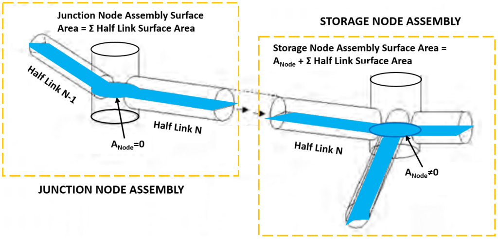
To update the heads (H) in a node at each time step, the concept of “node assembly” is utilized by SWMM by assuming a continuous water surface at a node and the conduits connected to it (mass conservation). A “node assembly” is defined as a node and half the length of each link connected to it.
As show in Figure 1, two types of node assemblies can be defined in SWMM: 1) a junction node assembly in which the junction node is a point with zero volume and surface area; and 2) a storage node assembly in which the storage node has both volume and surface area.
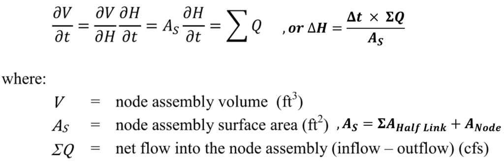
The node head is updated per Figure 2 equation – a mass conservation equation by accounting for the volume/head changes and the net flow into the node assembly.
A node is considered surcharged if the node’s water surface elevation exceeds the crown of the highest conduit connected to it. Traditionally in SWMM the node head is updated by different equations in a surcharged junction node and a surcharge storage node, which is referred as Extran surcharge method.
- When a junction node becomes surcharged there is no more volume available in the conduits of the node assembly (ANode=0 for a junction node) to balance the difference between inflow and outflow at the node and thus the node head update equation of Figure 2 is not applicable. SWMM uses another equation to update the junction node heads under surcharge condition (Figure 3) by enforcing the surcharge flow continuity condition. A smoothing function is applied within the transition zone between free surface flow and surcharged (pressurized) flow so the model does not become unstable when the governing equation is switched.

- In a surcharged storage node, the Figure 2 equation is still applicable and the node head is updated by dividing the storage node surface area only because of
 AHalf Link=0.
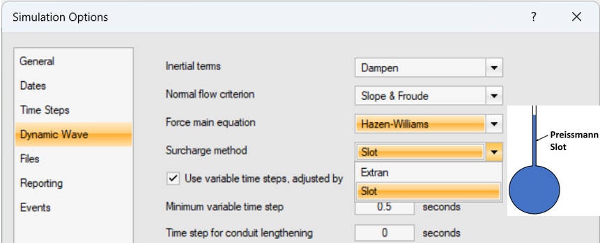
SWMM 5.1.013 introduced another method to handle surcharging – Slot (Figure 4). A Preissmann Slot is assumed on top of a closed conduit to give it an free flow surface area even under the surcharged condition so there is no need to switch to the Extran surcharge equation mentioned above for a surcharged node. Caution should be taken when switching to the Slot surcharge method since a SWMM model will behave differently, though sometimes the Slot option helps improve the model stability.
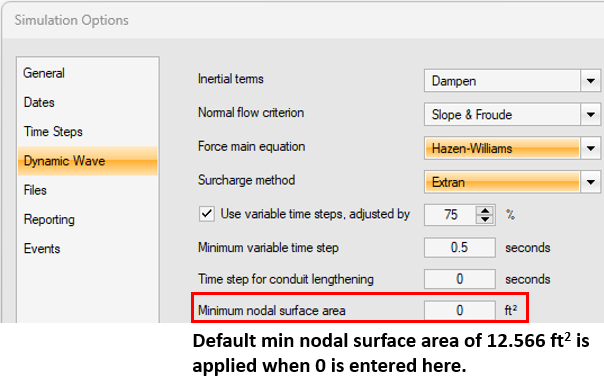
In SWMM, a minimum node surface area Amin (applicable for both junction and storage nodes) is required to prevent the Figure 2 equation solution from becoming unbounded (blowing up) if the node assembly surface area is too small: AS=Max(Amin , ![]() AHalf Link+ANode). The minimum node surface area default value is 12.566 sq ft (Dia=4.0ft manhole) but it can be overridden by the modeler (Figure 5). The minimum surface area does not play a role for a junction node under surcharge condition when the junction node head is updated per the Figure 3 equation.
AHalf Link+ANode). The minimum node surface area default value is 12.566 sq ft (Dia=4.0ft manhole) but it can be overridden by the modeler (Figure 5). The minimum surface area does not play a role for a junction node under surcharge condition when the junction node head is updated per the Figure 3 equation.
It is a common SWMM modeling practice to represent a manhole or an inlet as a junction node while define a detention basin as a storage node. By using a junction to model a manhole or an inlet, the underlying assumption is the area and volume of the manhole/inlet chamber are insignificant and thus ignored. However, if a modeler does not feel comfortable with this assumption or has other reasons to account for the manhole/inlet area and volume, a storage node can be used with a properly defined storage curve. In a storage node, the highest possible water surface elevation is its rim, since the surcharge depth or the ponded area option is not applicable. For this reason, the storage node rim elevation should be high enough to contain any possible peak HGLs, and similarly, its storage curve should include the depth-area pair data at its rim elevation.
Replacing a junction node with a storage node will end up with different modeling results especially if the node is under the surcharged condition. Furthermore, some modelers have reported that the storage node option for manhole/inlet might help improve a SWMM model’s stability. A weir or an orifice in SWMM models is often the reason of model instability, and one of the solutions is to replace its upstream and downstream junctions with storage nodes.
When storage nodes are defined as inlet and/or outlet nodes for an open channel link, it is important to not double account the volume by storage nodes and open channels. Usually the open channel link lengths need to be adjusted to only include the lengths outside the storage node area footprints.
Several PCSWMM models were created to observe the impact of replacing junctions nodes with storage nodes. Two scenarios were studied including a normal free surface flow condition and a surcharged flow condition.
Scenario 1 – Normal Free Surface Flow
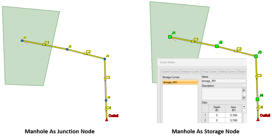
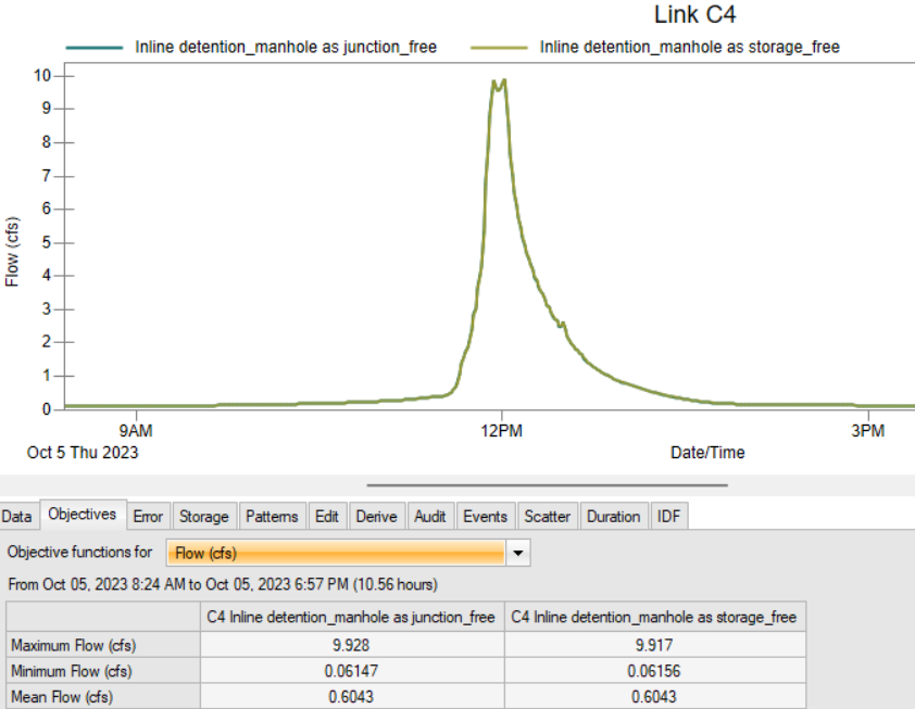
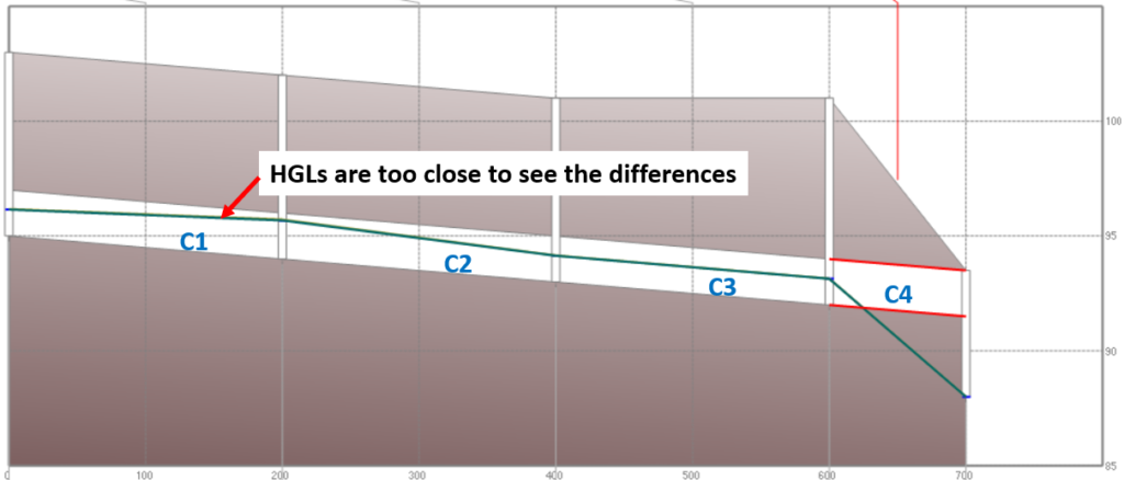
For Scenario 1, the storm sewer system is simply designed as a series of 24″ RCP (C1 to C3 – 200ft long and C4 – 100ft long) with a free outfall (Figure 6). The results show the differences of the flow rates and the HGLs between the two models are negligible (Figure 6 and Figure 8).
Scenario 2 – Surcharged Flow
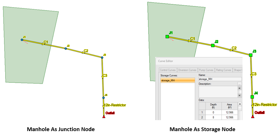
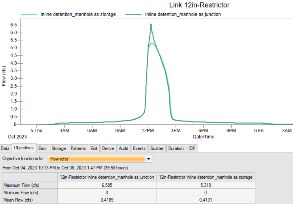
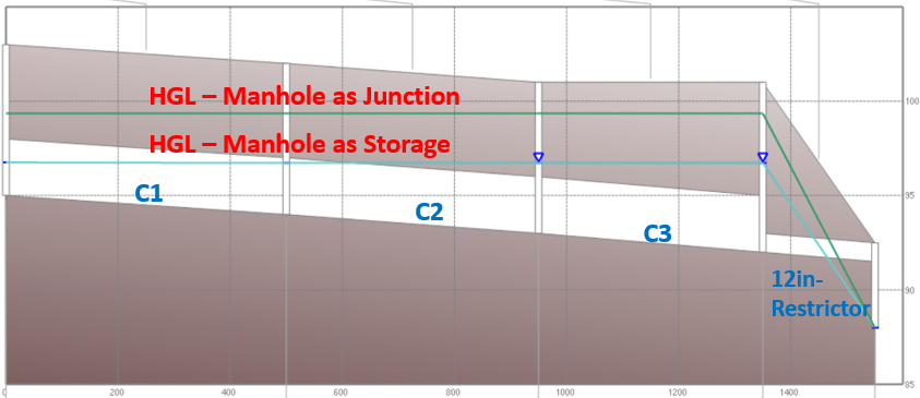
To model the surcharge condition, the storm sewer system consists of a series of 5’x3′ box culverts (C1 to C3) with a 12 inch restrictor (C4) at the outfall (Figure 9), which essentially makes it an in-line detention. The differences of the peak flow rates and HGLs between the two models are noticeable (Figure 10 and Figure 11) due to the fact that junction nodes and storage nodes use different equations to update the surcharged node heads. It may not be conclusive, but it appears a system in which junctions are modeled as storages nodes is more efficient at providing detention.
Leave a Reply