Initial Conditions, Restart File, Warm up, 2D Ramp up
For unsteady state 1D and 2D HEC-RAS models, initial conditions must be set up appropriately to not make the model crash or become unstable at the beginning of the modeling. Initial conditions are set up in Unsteady Flow Data Editor’s Initial Conditions tab (Figure 1).
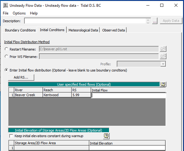
You can specify a Restart File by using an output file from a previous run to establish the initial conditions for you current run. By applying the concept of Restart File, if you need to run a long simulation time, you can divide the total simulation time into several shorter periods (Period 1, 2, 3,…) and the output file at the end of Period 1 can be used as the initial condition Restart File of Period 2.
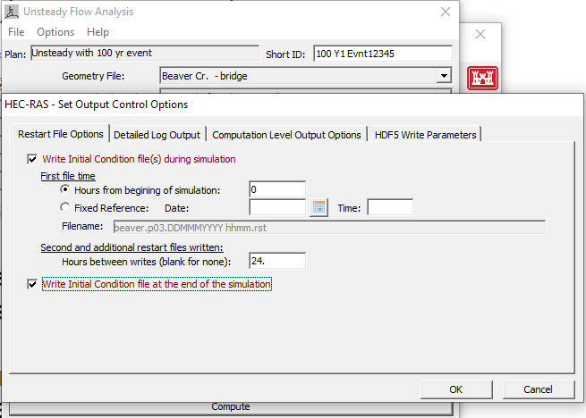
To generate a restart file for initial conditions, a “restart” unsteady flow data file needs to be created first. The inflow hydrographs is a constant value equal/close to the initial flow value (at time = 0.0) of the normal model run. The stage hydrographs can be a step down one starting from an arbitrary high value (for example, equal to the most upstream cross section invert or even higher) and gradually decreasing to a reasonable value that would be expected at time=0.0 for the normal model run. Finally, a “restart” plan file will be needed which includes the “restart” unsteady flow data and the normal model geometry file. Open the “restart” plan and go to Unsteady Flow Analysis window and click Options —> Output Options … to set up restart files per your needs (Figure 2).
Another option to establish initial conditions are to enter flow data for each reach for an 1D model (Figure 1) and have HEC-RAS perform a steady-state flow backwater run to compute the corresponding stages at each cross section. The initial flow data can be changed at any cross section but at a minimum a flow at the upper end of each river reach must be provided. When users provide initial flow data, the value entered should be the same as or close to the first flow value of the boundary condition flow hydrograph (start of simulation).
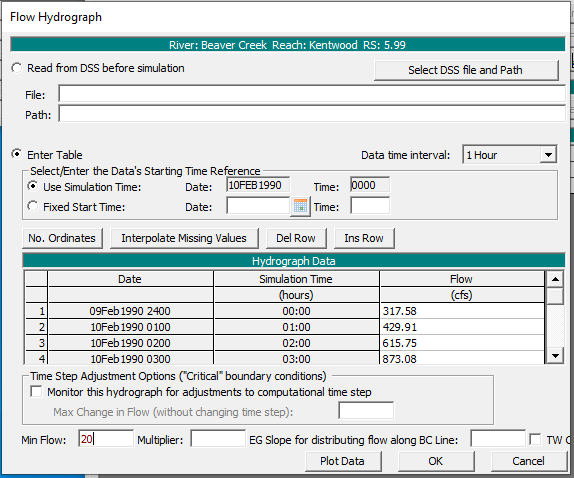
By default, for a dentritic river system, if users leave the initial flow at the upper end of each river reach blank, HEC-RAS will use flow data from the first value of the boundary condition flow hydrographs – this is a very common practice for unsteady state HEC-RAS modeling. If users type in a min flow in unsteady flow data editor (Figure 3), the practice of leaving initial flow data blank will also recognize this min flow setting (HEC-RAS will pick up the greater of min flow and first flow value of flow hydrograph as initial flow). In the example shown in Figure 3, since Min Flow is entered as 20 cfs while the first flow value is 317.58cfs, HEC-RAS will set up the initial flow as 317.58 cfs; however, if in Figure 3, the Min Flow is 500cfs, HEC-RAS will set up the initial flow as 500cfs.
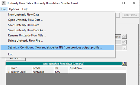
A third option is available to set the initial flow and stage from a profile from a previous run. The third option can be selected from the File menu of Unsteady Flow Data Editor: File —> Set Initial Conditions (flow and stage for 1D) from previous output profile … (Figure 4). After clicking this command, users can select a plan and profile from a previous run (Figure 5) to set up the initial conditions.

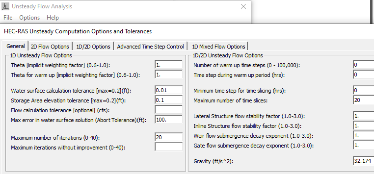
At the start of a simulation run, if a model experiences numerical stability issues, user can turn on warm up option by go to Unsteady Flow Analysis —> Options —> Computation Options and Tolerances … (Figure 6). Under the General tab as shown in Figure 6, users can enter a number for warm up time steps (by default this value is zero which means no warm up period). Time step during warm up period (hrs) will use the simulation time step if it is left by default value (0), or users can enter a different time step. The warm up time setting is to be applied in both 1D and 2D domains.
HEC-RAS default setting is not to perform a warm up period, however if a model becomes unstable at the beginning of a run, users can have HEC-RAS run a number of iterations before the start of the simulation in which all inflows are held constant (warm up). Warm up run does not advance in time and the actual simulation only starts after warm up run ends.
If a 2D flow area has been attached with external boundary conditions (flow hydrographs or stage hydrographs) or is directly connected to an 1D river cross section (not through a lateral structure) and therefore flow will be coming into or out of the 2D area at the beginning of the simulation, the 2D area Initial Condition Ramp Up Time option must be enabled. The ramp up time (Figure 7) under 2D Flow Options Tab of Computation Options and Tolerances window is different from the warm up period. The ramp up option allows users to specify a time (in hours) to run the computations for the 2D Flow Area, by slowly transitioning the flow boundaries from zero to their initial value, and the stage boundaries from a dry elevation up to their initial wet elevation. Users specify the total “Initial Conditions Time” (2 hours, for example) and a fraction of this time for ramping up the boundary conditions. A value of 0.1 means that 10% of the Initial Conditions time will be used to Ramp Up the boundary conditions to their initial values, the remaining time will be used to hold the initial boundary conditions constant, but allow the flow to propagate through the 2D Flow Area, thus giving it enough time to stabilize to a good initial condition throughout the entire 2D Flow Area. If initial conditions time is 2hrs and the ramp up fraction is 0.1, then HEC-RAS will run by transitioning from zero to initial condition values within 2hr*0.1=0.2hrs and for the rest 2hr*0.9=1.8hrs, HEC-RAS will run by holding the initial conditions constant.
Warm Up option is for the entire HEC-RAS model elements including 1D and 2D, however, Ramp Up option is for 2D domains only and it must be turned on if at the beginning of the simulation there is water flowing into or out of a 2D area to establish initial conditions. Normally 2D ramp up happens before the start of the overall model Warm Up.
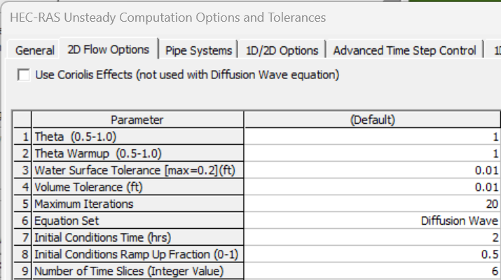
Sometimes, a 2D area requires a smaller time step than the one required by 1D modeling, for example, a 2D cell size is 100ft x 100ft while the 1D river cross section spacing is 600ft, so an appropriate 2D time step may be around 100ft/5fps x 1.0=20 sec (assume Courant number needs to be 1.0 and the wave velocity/celerity is 5.0 fps) and the 1D time step can be estimated as 600ft/5fps x 1.0=120sec or 2.0 min. If the overall unsteady modeling time step is chosen as 2.0 min, the 2D modeling time step can be sliced to 20 seconds by entering 6 for Number of Time Slices (Integer Value) in Figure 7. Different values for Number of Time Slices can be set for each 2D flow area.
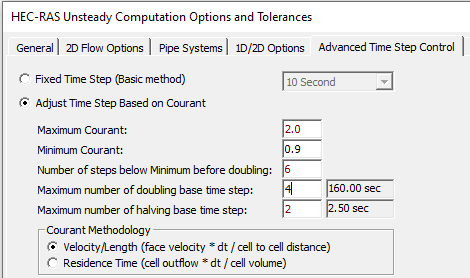
To reduce the overall model run time, the time step can be adjusted based on Courant Number (Figure 8) under Advanced Time Step Control Tab of Computation Options and Tolerances window. If the flood wave is rising and falling rapidly (depth and velocity are changing quickly), maximum Courant probably needs to be close to 1.0 with a very small time step (dam breach analysis). Usually, the maximum Courant Number can be set up as 2.0 or 3.0 for most applications so the adjusted time step is not too small.
The Minimum Courant number should be less than half of the maximum Courant number. In Figure 8, the maximum Courant number is 2.0 and the minimum Courant number is set up as 0.9. In order to prevent HEC-RAS from changing time step too frequently, the number of steps below minimum before doubling can be chosen as a value between 5-10.
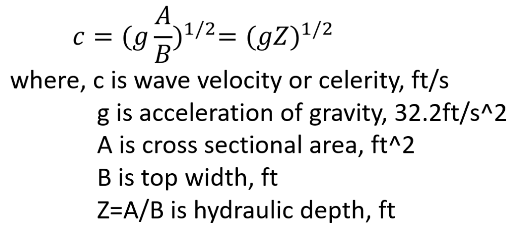
Note: how to estimate wave velocity or celerity c – refer to the equation is Figure 9. An example: assume the hydraulic depth is 1.0ft, c=(32.2 x 1)^(1/2)=5.7 fps.
Leave a Reply