Node Flooding, Surcharge, and Ponding in PCSWMM and EPA SWMM
In 1D storm sewer network modeling, it is important to understand how a modeling tool handles the system flooding or overflowing which will impact HGL and flow calculations in the conduits. A post on how to properly model 1D flooding and ponding in XPSWMM can be found here, and this post is to focus on PCSWMM and EPA SWMM. PCSWMM employs the latest EPA SWMM H&H calculation engine while XPSWMM uses its own calculation engine even though it originated from EPA SWMM engine several decades ago. The basic flooding/ponding principles from the previous XPSWMM post are still valid, however, PCSWMM and EPA SWMM do treat the topic a little bit differently as explained below.
As a responsible H&H modeler, you do not want water to get lost from your 1D storm sewer system (Figure 1) unless it outfalls to a receiving waterbody or is diverted to somewhere outside the system on purpose. When a 1D storm sewer system is overwhelmed under extreme storm events, you have to figure out appropriate ways to handle flood water which can not be accommodated inside the subsurface storm sewer pipes (usually designed for 2-yr, 5-yr or 10-yr events).

PCSWMM and EPA SWMM have several means to tackle the issue including Surcharge Depth, Ponded Area, Storage Node, and a dual drainage system.
- Surcharge Depth
A non-zero surcharge depth can be applied to a junction so the HGL at this junction can go up as high as Rim Elevation + Surcharge Depth. An arbitrary high value should be entered as Surcharge Depth so no water will come out of this node. This option is similar to the “Sealed” option of XPSWMM and thus it may be (should be) used at bolted manhole locations. For other junctions where water can actually spill out, its application is probably only suitable for a preliminary level study since an unrealistically high HGL because of the surcharge depth will impact the hydraulics calculation in the conduits upstream or downstream.

- Ponded Area
A non-zero ponded area can be provided at a junction and with the “Allow ponding” radio button being enabled (Figure 3) , any excessive water can be temporarily stored in this ponded area above the rim of the junction. When the conduit capacity become available, the temporarily ponded water will re-enter the storm sewer system. Unlike XPSWMM where a conic shaped ponded area is defined, the ponded area in PCSWMM and EPA SWMM has a constant surface area value regardless of the water depth.


It is preferable to apply the ponded area option to a junction in a low spot such as a sag. It does not make a lot of sense to enable the option at an on-grade junction, even though a lot of modelers are doing it anyway. For an on-grade inlet or manhole, a dual drainage system is more appropriate to handle excessive water coming out of it.
The determination of a ponded surface area is tricky: it may be calculated as a certain percentage of a subcatchment area, or can be estimated by checking the inundation maps to see how big an area can be flooded around the junction. A trial and error method is often necessary to finalize its value so the modeling results are reasonable and acceptable. An important fact to keep in mind is if a ponded area is too small, the model again may end up with some unreasonably high HGL.
The ponded area option does not work simultaneously with the surcharge depth option, and if both options are enabled at a junction, the surcharge depth option will be ignored.
- Storage Node
The ponded area option is a simplified method to simulate surface flooding by assuming a constant surface area above the junction rim. To more accurately model the situation without resorting to a coupled 1D-2D model, a junction can be converted to a storage node associated with a storage curve to define its depth-area relationship from node bottom (depth=0) to a depth larger than the expected peak values (Figure 5).

The Surcharge Depth or the Ponded Area option is not available for a storage node. For a more detailed discussion about the differences between a storage node and a junction node, refer to this post.
- Dual Drainage System
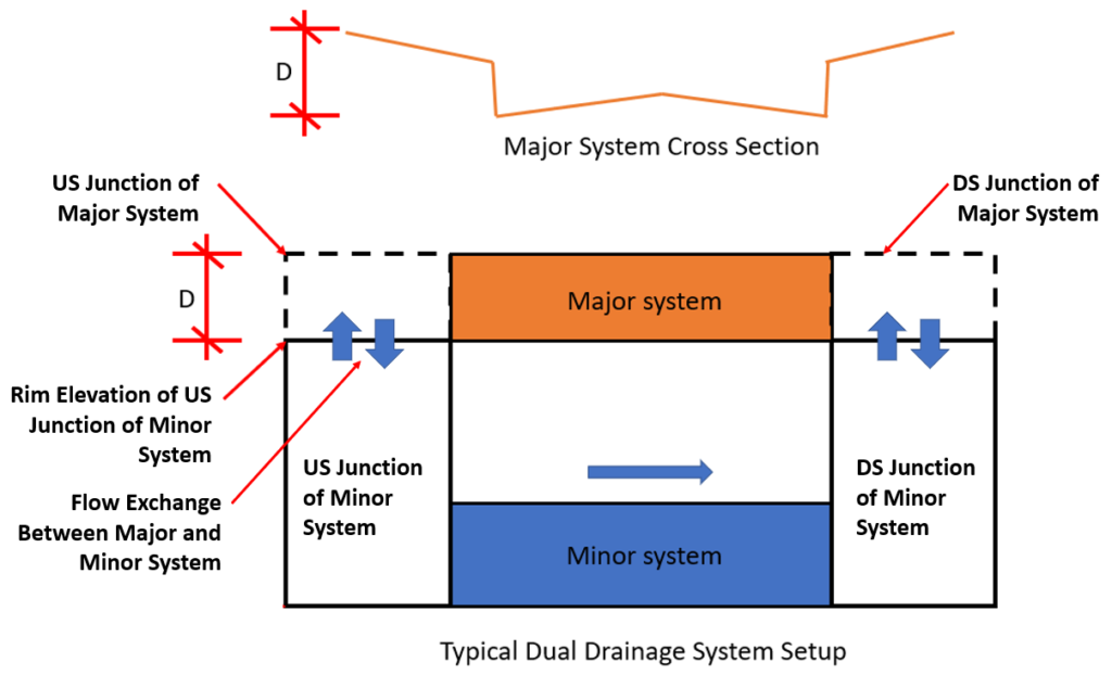
Like XPSWMM, PCSWMM can also model a dual drainage system including a minor system – subsurface storm sewer network and a major system – open channel flow in street/overland/ditch (Figure 6). The flood water is to be routed through the major system and it will re-enter the minor system when the minor system capacity becomes available or outfall to a receiving waterbody at the end.

PCSWMM Dual Drainage Creator Tool can be used to create a major system parallel to the existing minor system:
1. Open Street Editor to create a representative street section for the major system (Figure 7).

2. Select the minor system conduits where the major system is to be created, and open Dual Drainage Creator Tool (Figure 8).

There are 3 options for inlet control including None (no restriction, free flow), Use inlet or Outlet. If the Outlet option is chosen, the flow exchange between the minor and major system nodes is controlled by the outlet rating curve (Figure 9). Optionally, a modeler can convert the outlet to an orifice, for example, using a side orifice to represent a curb inlet opening (Figure 10) or a bottom orifice for a grate inlet.


Leave a Reply