Culvert Analysis in HY-8, HEC-RAS, XPSWMM, and InfoWorks
A culvert is a closed conduit with a relatively short length connecting two open channels or water bodies. From a hydraulic analysis perspective, usually a culvert does NOT have too big an opening area (for example, 20ft or wider span, otherwise, it may be better modeled as a bridge) or is NOT too long/too complicated (otherwise, it maybe better modeled as a storm drain system). Energy is required to force water to flow through a culvert and this energy takes the form of an increased water surface elevation on the upstream side of a culvert (HW or headwater in Figure 1). Since a culvert usually has a smaller hydraulic opening area than the upstream and downstream channel cross sections, it therefore works as a “restrictor” in many scenarios which results in an even higher water depth at its inlet side. A primary goal of culvert design is to ensure that the proposed culverts are sized adequately so that the headwater (HW) is not going to rise so high to overtop the embankment or flood surrounding properties.
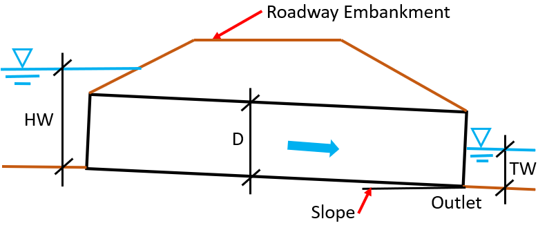
A culvert’s hydraulic characteristics is complicated, and it is a common practice to apply the concepts of inlet control and outlet control to simplify the problem. Inlet control happens when the culvert inlet (entrance) capacity is less than culvert barrel capacity and thus how much water would be accepted by the culvert is determined (controlled) by the inlet (Figure 2). Outlet control flow occurs when the culvert barrel capacity or tailwater condition limits how much water can flow through the culvert (Figure 3).
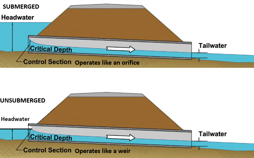
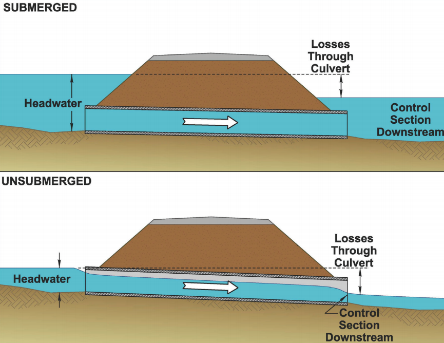
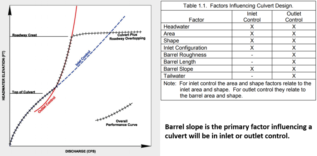
The control section of inlet control is located just inside of entrance of the culvert (Figure 2) and after passing through critical depth at this control section, the flow becomes “supercritical flow” that is usually shallow with high velocity. The culvert operates as an orifice (entrance submerged) or a weir (entrance unsubmerged) under inlet control condition. The control section of outlet control is at the culvert downstream end (barrel exit or further downstream, Figure 3) and its flow is either “subcritical flow” or “full flow (pressure flow)”. Inlet control factors include headwater, inlet area, inlet shape, inlet configuration, and barrel slope. For outlet control, a culvert’s performance is not only impacted by these inlet control factors but also by barrel shape & area, barrel length & slope, barrel roughness, and tailwater. In culvert design both inlet control and outlet control are to be analyzed and the headwater depth will be determined by whichever is “more” restrictive – greater headwater depth of the two (Figure 4).
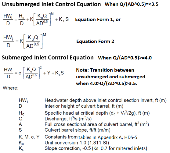
The National Bureau of Standards (NBS) and FHWA developed a set of equations and nomographs to describe the relationships between headwater (HW) and discharge for various sizes of culverts and inlet types (Figure 6) (Appendix A and C of FHWA HDS-5). These inlet control equations are empirical equations based on lab tests. A well-designed inlet structure will “funnel” or “induce” flow into culvert barrels smoothly with less turbulence (thus less head loss) and at the same time it should provide sufficient structural integrity, travel safety, and/or erosion protection.
To solve the above inlet control equations, software like HY-8, HEC-RAS, XPSWMM requires modelers to enter Chart # and Scale # or inlet configurations per the tables in Appendix A of HDS-5 (Figure 7), and the corresponding K, M, c, Y values which are already coded in the software are applied automatically based on the inputs. Other software, for example, InfoWorks ICM, asks modelers to provide K, M, c, Y values directly.

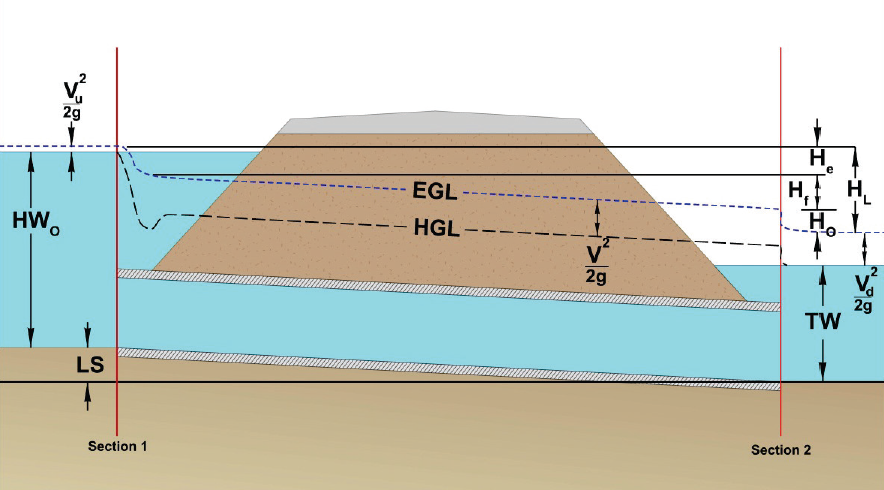
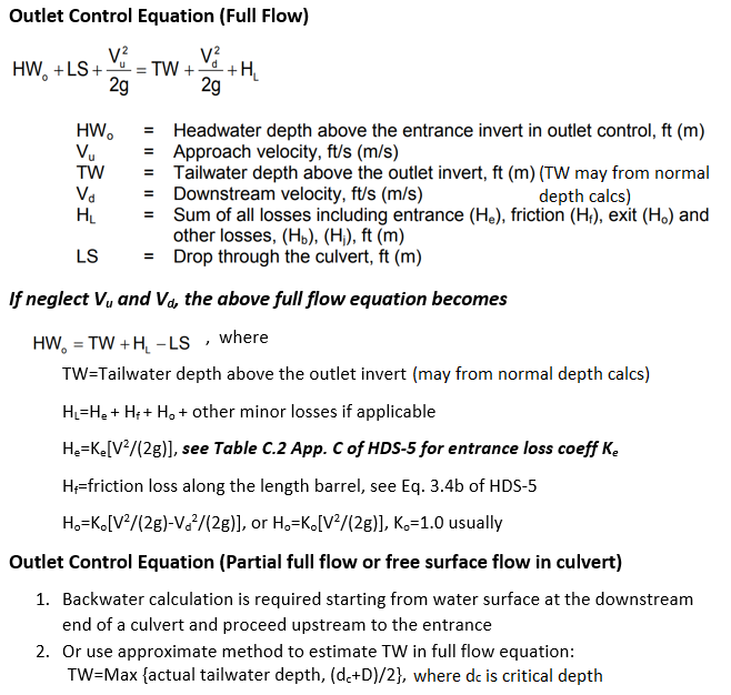
Culvert outlet control hydraulics can be calculated based on the theory of energy balance when the culvert is flowing full (Figure 8 and Figure 9) according to FHWA HDS-5. When culvert is flowing partially full or having a free surface flow inside the barrel, a backwater calculation is needed starting from water surface at the downstream end of the culvert and proceeding upstream to the entrance of the culvert (Figure 9). To avoid backwater calculation, an approximate method developed by FHWA can be used by estimating a new or hypothetical TW for use full flow equation (Figure 10). To apply the approximate method of estimating TW, the culvert barrel must flow full partially and the resulted headwater can not be less than 0.75D.

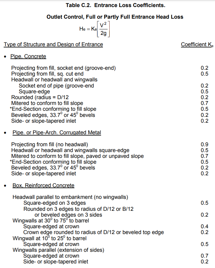
The entrance loss coefficient can be found at Table C.2, Appendix C of HDS-5 (Table 1). The exit loss coefficient usually is 1.0 and it can vary between 0.3 and 1.0 per HEC-RAS Hydraulic Reference Manual.
HY-8, HEC-RAS, XPSWMM (including PCSWMM and EPA SWMM), and InfoWorks partially or fully implemented FHWA HDS-5 inlet control equations and outlet control energy routines as summarized in Table 2

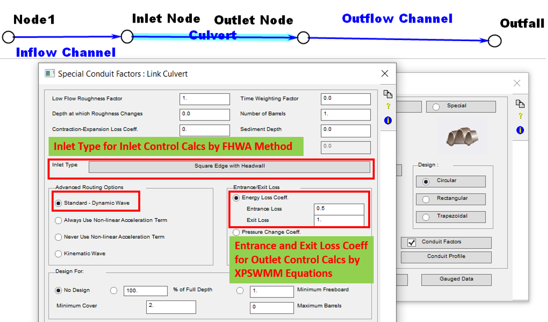
When using dynamic wave routing, XPSWMM (including PCSWMM and EPA SWMM) calculates flow through any conduit using outlet control with or without entrance/exit loss being considered. If a conduit is also assigned an inlet type or culver code, XPSWMM will calculate another flow using FHWA inlet control equations. The final conduit (culvert) flow rate is chosen as the smaller of the two based on inlet control and outlet control conditions.
To turn on culvert calculation routine in XPSWMM, click and check on “Conduit Factors” option in Conduit Data Edit window, and select Inlet Type for inlet control calculation and provide entrance loss and exit loss coefficients for outlet control calculation as shown in Figure 11A.
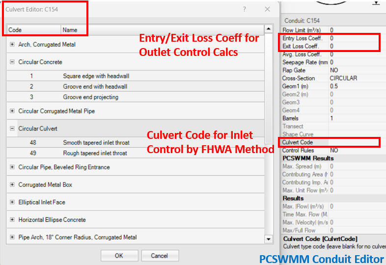
In PCSWMM or EPA SWMM, if a conduit is to be modeled as a culvert, the culvert code (for FHWA inlet control method) can be selected in Conduit Editor as shown in Figure 11B.
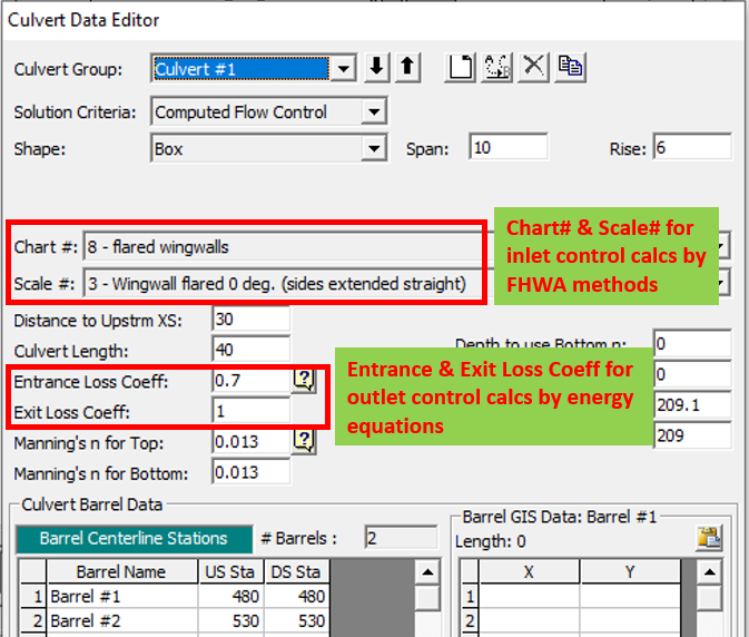
To model a culvert (inline or lateral structure, or SA/2D connection) in HEC-RAS, the culvert shape and its Chart# and Scale# are to be provided (Figure 12), which can be found from Table 6-6 of HEC-RAS Hydraulic Reference Manual or Appendix A of HDS-5. Entrance and exit loss coefficients are used for outlet control calculation by energy equations.
Inlet configuration is a required input in HY-8, similar to XPSWMM (Figure 13).
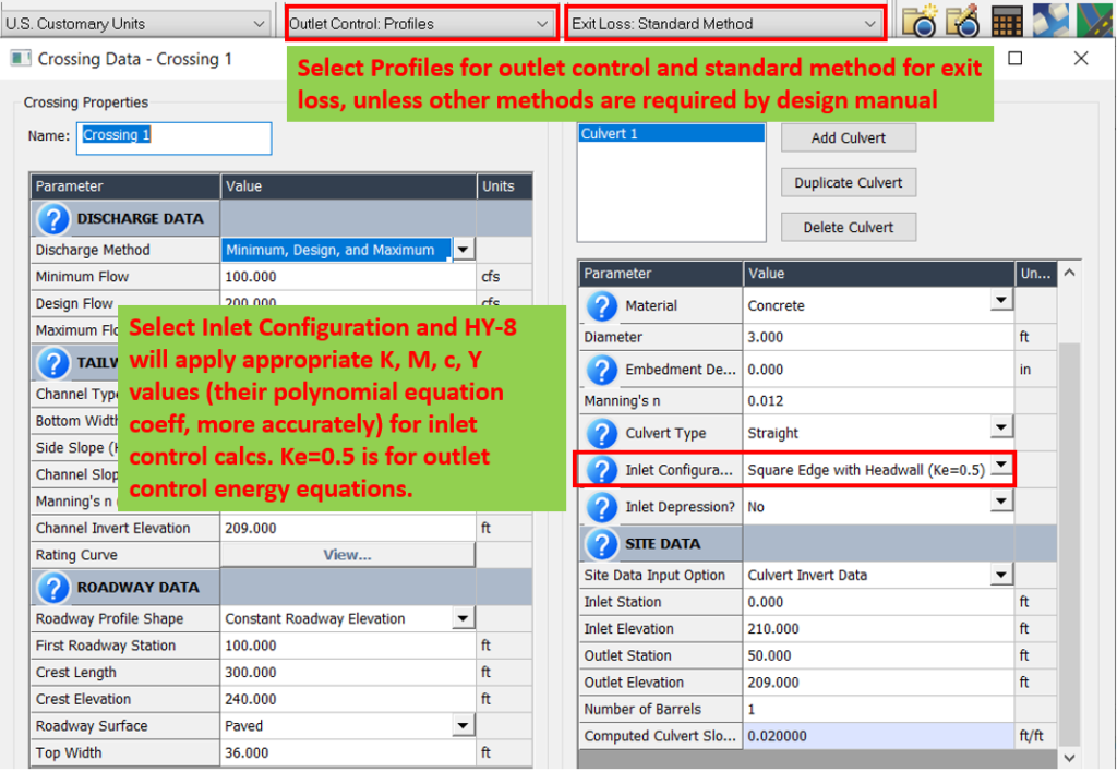
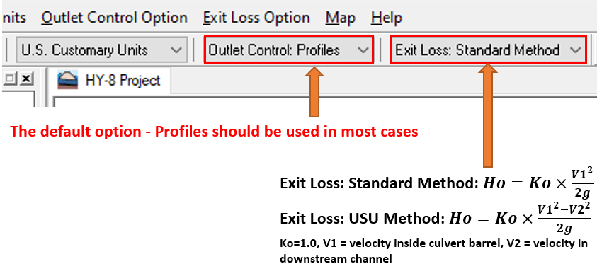
In HY-8, two exit loss methods are available and the difference is explained in in Figure 14. The standard exit loss method is sufficient for applications where downstream channel velocity can be neglected.
InfoWorks ICM models inlet of a culvert by a distinctive link type of “culvert inlet” (Figure 15). The culvert barrel itself is to be modeled as a conduit with “None” as US/DS headloss type in InfoWorks. The K, M, c, Y values for inlet control equations need to be entered directly, plus inlet headloss coefficient Ki for outlet control energy equations. An inlet can be modeled as an outlet when flow direction reverses, and under this scenario setting modelers needs to provide outlet headloss coefficient Ko.
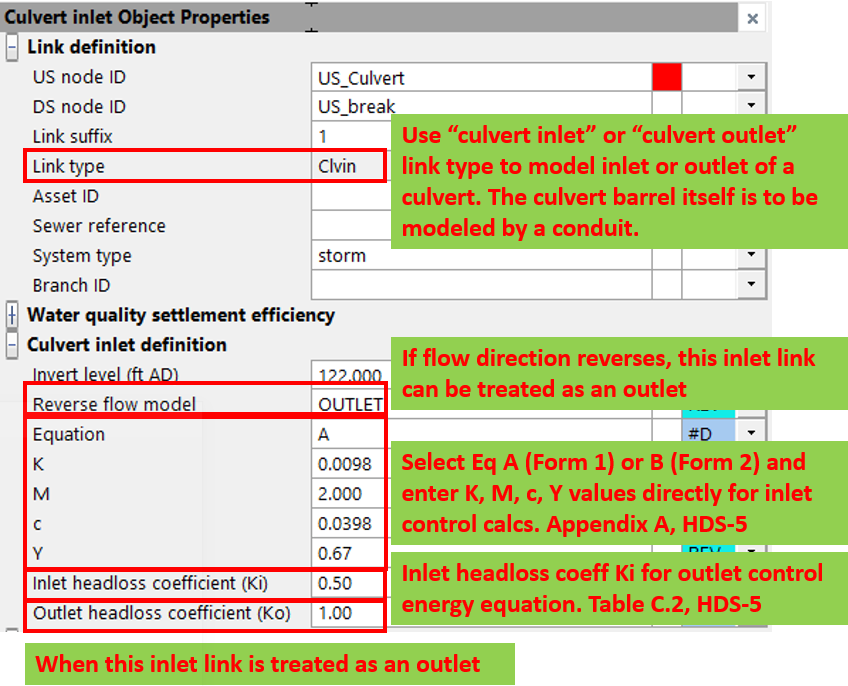
Similarly InfoWorks ICM models outlet of a culvert by a distinctive link type of “culvert outlet” and outlet headloss coefficient Ko is to be provided by the modelers for outlet control energy equations. An outlet can be modeled as an inlet when flow direction reverses, and under this scenario setting the K, M, c, Y values for inlet control equations are needed, plus inlet headloss coefficient Ki.
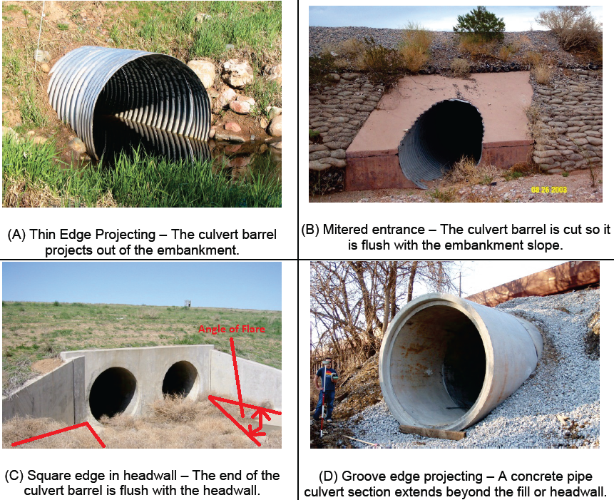
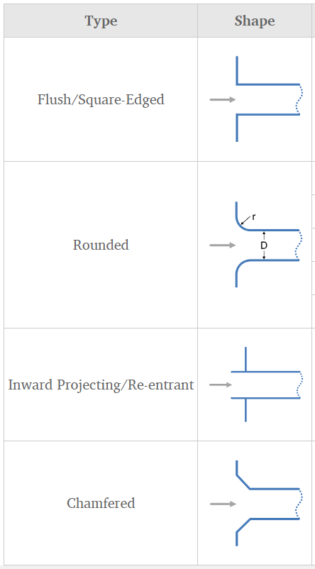
As FYI, some typical entrance designs are illustrated in Figure 16.
Leave a Reply