Comparing HEC-RAS Pipe Networks Function With SWMM
Starting from Version 6.6, HEC-RAS is able to model stormwater pipe networks including conduits (pipes) and nodes (manholes or inlets). By coupling stormwater pipe networks with HEC-RAS 2D surface, modelers can now analyze an urban storm sewer system’s capacity and and its interaction with streets, parking lots, and other ground surfaces. In the past, to study an urban flooding problem, often the modelers have to rely on commercial stormwater modeling tools such as PCSWMM and Infoworks ICM.
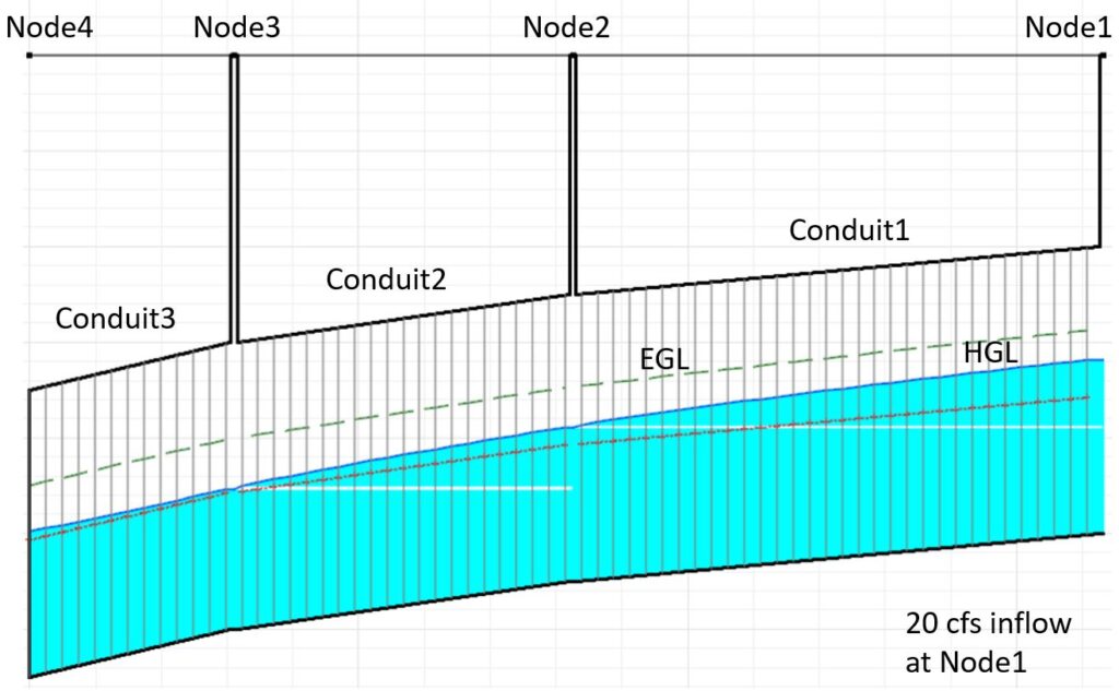
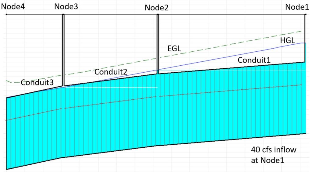
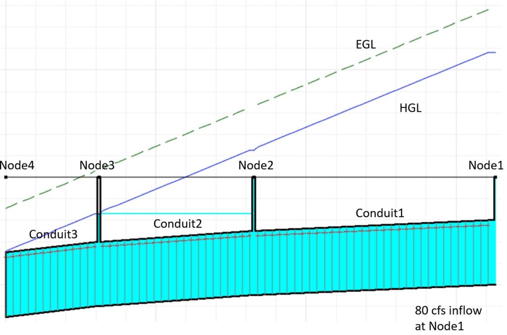
A simple 1D pipe network consisting of 3 nodes, 3 pipes, and 1 outfall was created and modeled in HEC-RAS V6.7 Beta 3 and SWMM 5.2.4 respectively to compare the 1D dynamic flow routing capabilities of the two tools (Figure 1). 3 different inflows (20 cfs, 40 cfs, and 80 cfs) were loaded into Node1 to model free surface flow, surcharging, and node flooding scenarios. The boundary condition at Node4 was set up as stage hydrograph with fixed stages at 895.0 for 20cfs inflow and 896.5 for 40cfs and 80cfs inflows.
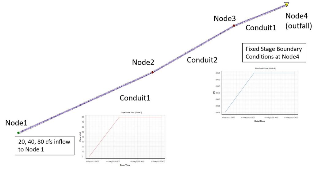
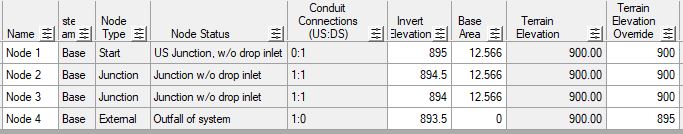
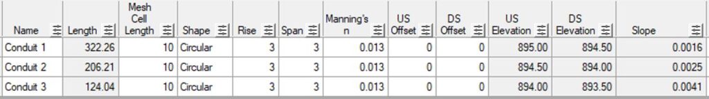
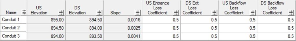
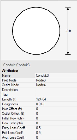
The pipe networks modeled in HEC-RAS 6.7 and SWMM are exactly the same in terms of conduit and node parameters (Figure 2 and Figure 3), inflows, and boundary conditions. The study is to focus on the two modeling tools’ 1D dynamic flow routing function so there is no 2D surface coupled with the 1D pipe network in either of the models.
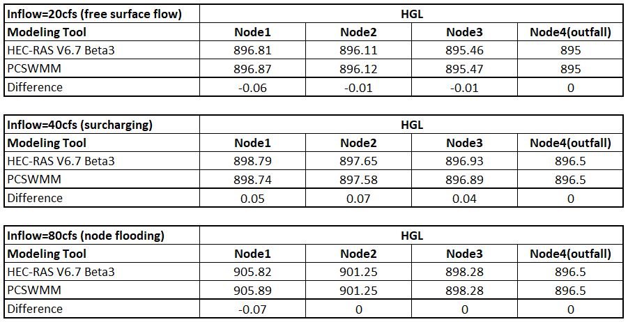
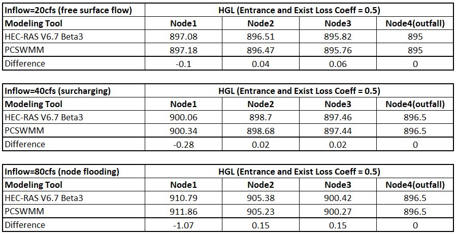
The results from the two modeling tools are in close proximity regarding the HGL at the three nodes with the biggest difference being 0.07 ft as shown in Table 1. In SWMM to support the scenario of node flooding, the three nodes were assigned a surcharge depth of 20 ft, which essentially “bolted” the nodes. In HEC-RAS, this kind of setting is not necessary since by default, the HEC-RAS nodes are “bolted” or “sealed” so the HGL can rise above the node rim elevations.
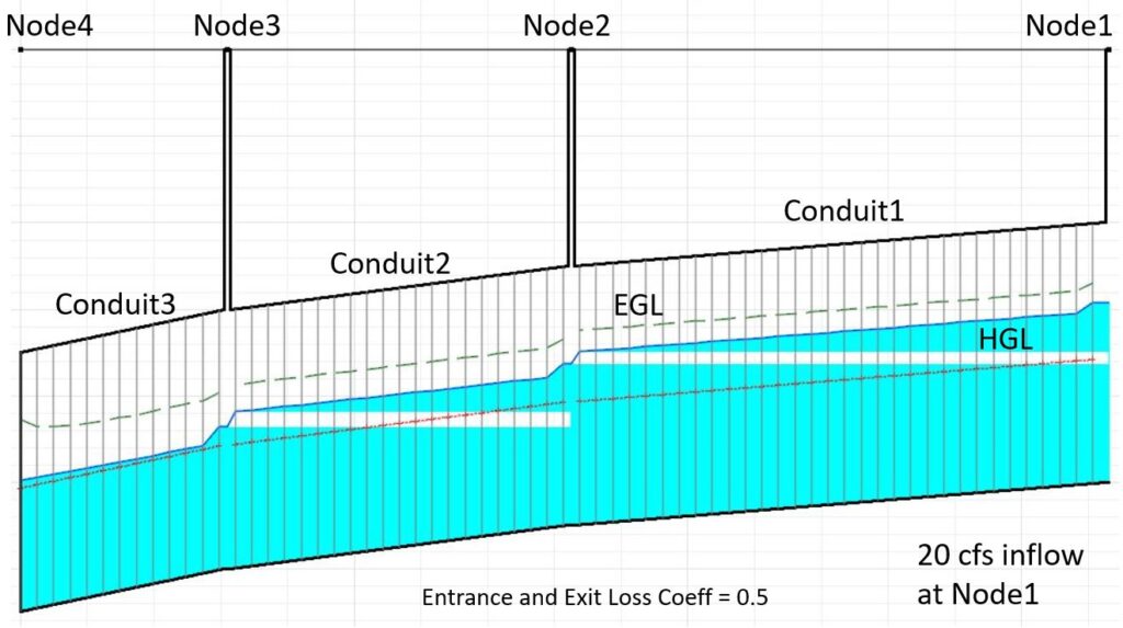
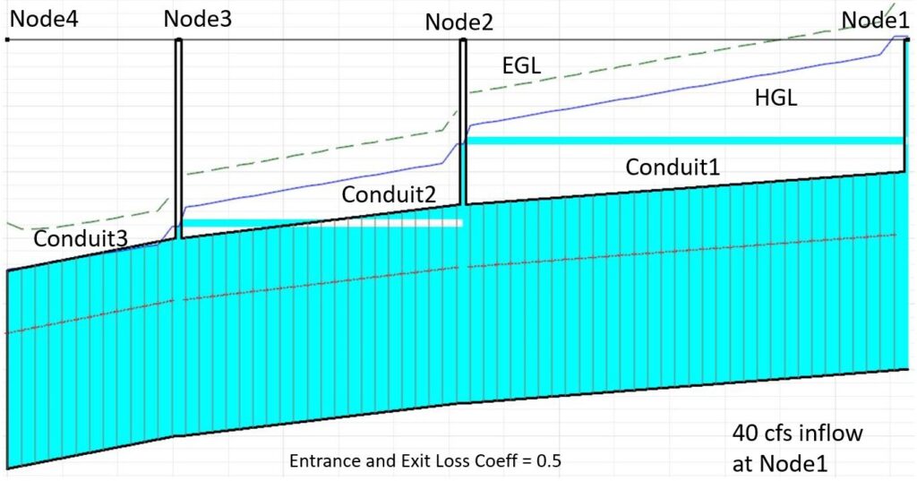
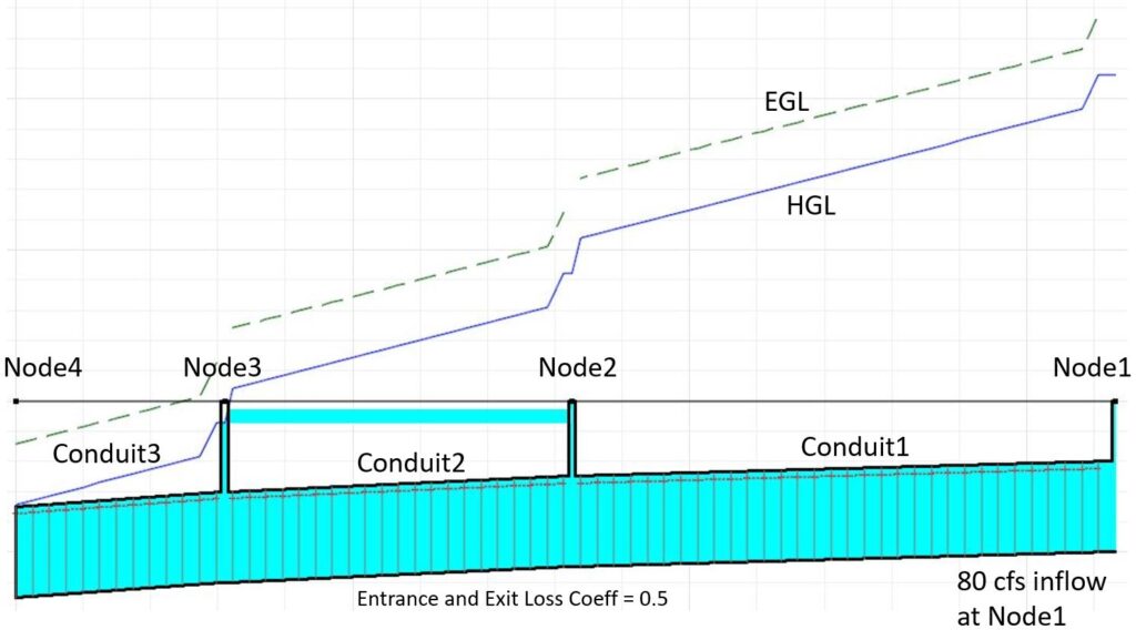
The above test was re-run by assigning entrance and exit loss coefficients of 0.5 to each pipe (Figure 7 and Figure 8).
The two models ended up with close HGLs (Table 2) even though it appears the differences are larger than those when the entrance and exit loss coefficients = 0.0.
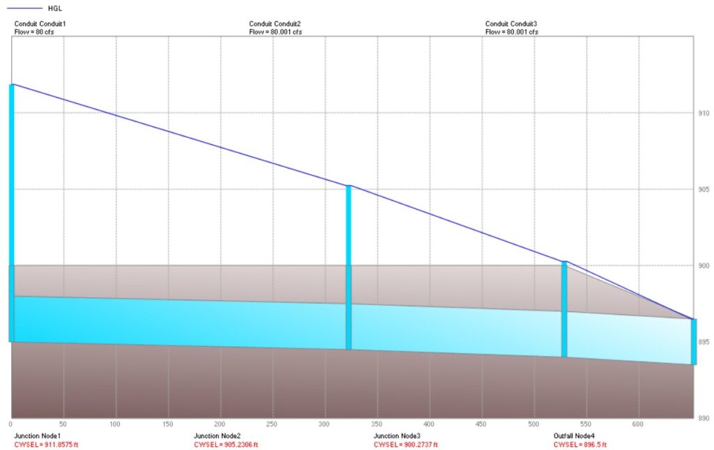
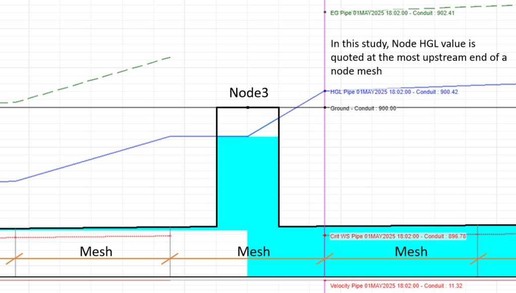
SWMM and HEC-RAS calculate the entrance and exit losses at the node locations differently, which may explain why the HGL differences are larger when the entrance and exit losses are not zero. In SWMM, entrance and exit losses are treated the same as the friction loss over a pipe and thus there is only one single HGL at nodes (Figure 12); while in HEC-RAS, as shown in Figure 13, the pipes and nodes are subdivided into different mesh segments and the entrance and exit losses are calculated explicitly at the node mesh locations. In other words, HEC-RAS pipe network has more spatial resolutions than SWMM dynamic wave routing solver.
It should be noted that the above discussions are preliminary and some scenarios may not even be realistic, like when inflow = 80cfs the most upstream node HGL is more than 10ft higher than the node rim elevation. In the real world, a more reasonable result probably will be: before HGL reaches 10ft higher than rim elevation, the manhole cover will be blown up and the storm water will gush out and become 2D surface flow. Furthermore, other HEC-RAS pipe network capabilities are not evaluated, such as the node (inlet) flow capture function when it works as a weir or orifice, or the 1D/2D flow coupling and interaction.
Leave a Reply