How Many Breaklines Are Enough In A HEC-RAS 2D Model?
Breaklines are crucial in HEC-RAS 2D modeling because they control how the cell mesh aligns with important terrain features. This directly improves the accuracy and stability of flow simulations. This article covers practical guidance on how to effectively add breaklines in HEC-RAS 2D models. Before exploring specific techniques, it is important to review the fundamental concepts of 2D hydraulic modeling in HEC-RAS to better understand the value of breaklines.
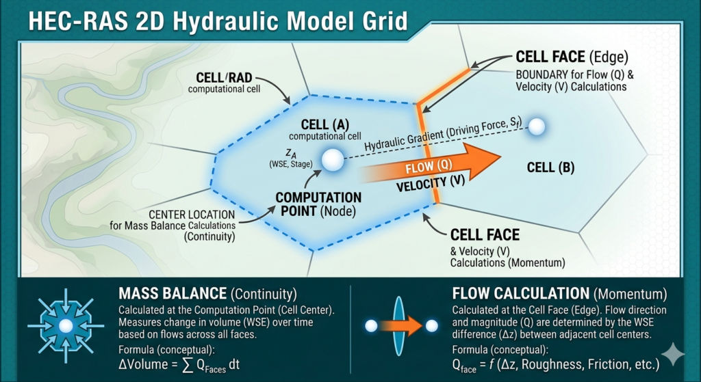
HEC-RAS 2D is a remarkably efficient hydraulic modeling tool, largely because it uses a subgrid terrain approach by overlaying a relatively coarse computational mesh on top of a detailed terrain model (DEM). Before running any hydraulic calculations, HEC-RAS pre-processes the mesh and extracts detailed geometric data for every single cell and cell face.
- For every cell, HEC-RAS samples the underlying high-resolution terrain to build a Stage-Volume relationship. The model knows exactly how much water volume the cell can hold at any given water surface elevation. If water enters a cell, it doesn’t instantly cover the whole cell and instead, It fills the lowest portion of the cell first.
- For every cell face, HEC-RAS samples the terrain cross-section to build curves for flow areas, wetted perimeters, and Manning’s n. The flow rate at cell faces is driven by the head difference between two adjacent cells and solved by momentum equations (shallow water or diffusion wave).
While the HEC-RAS subgrid system is excellent, it has a physical limitation: it cannot stop water from passing through a cell face if the face itself is poorly positioned. This is where breaklines become necessary (Figure 2).
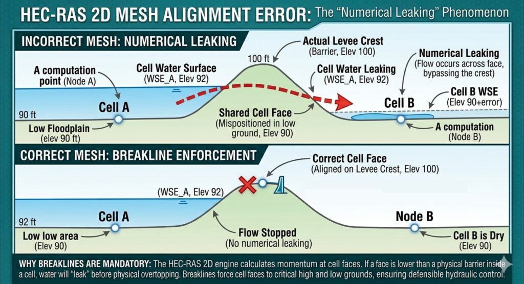
HEC-RAS User’s Manual suggest that breaklines shall be applied to locations which control or block water flow like a levee, roadway embankment, or a natural ridge/high ground. However, If you try to map every single undulation, ridge, and bump in a real-world terrain, your mesh will become unmanageable. In practice, you don’t need (and should not add) breaklines everywhere on high ground since breaklines should be applied as a targeted tool, not a blanket solution for all terrain variations. For example, if a plateau is 200 feet wide and your cells are 50 feet wide, you probably don’t need a breakline. The cells will naturally conform to the climb and descent of the plateau. But if a levee is only 15 feet wide and your cells are 50 feet wide, the cell faces will span across the levee, causing the “water leaking” and this is where a breakline is necessary. In areas having small rolling hills and minor ridges water will find its way around or over them naturally and therefore a breakline is not usually required.
An experienced modeler will start a HEC-RAS 2D model having a simple meshing scheme with reasonable cell sizes and obvious breaklines. After several test runs, additional breaklines can be added into the model selectively to prevent water from leaking through high ground (fragmented or unrealistic inundation) or eliminate irregular depth/velocity patterns along linear features.
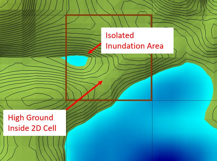
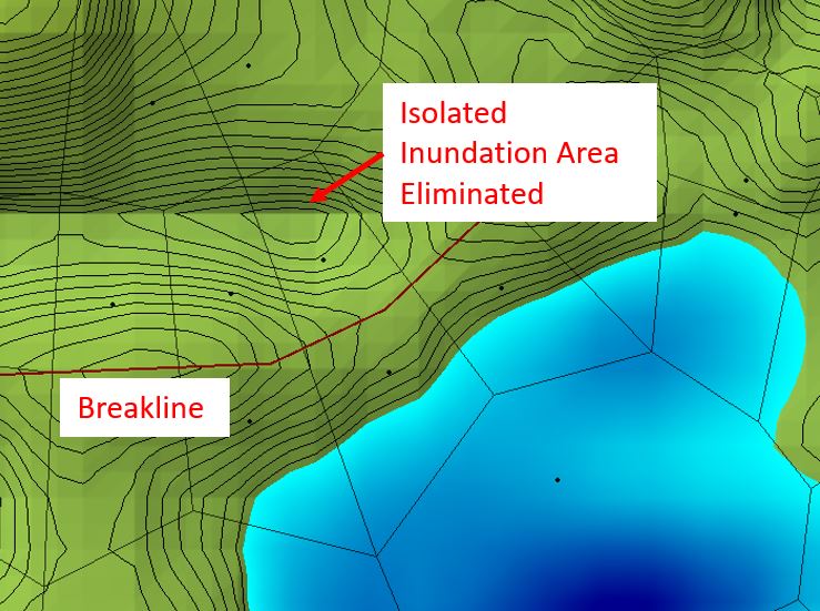
When examining the 2D Depth or WSE results, some isolated areas may be inundated but probably shouldn’t. In Figure 3, an isolated inundation area is observed because the high ground which is supposed to block the water flowing from the cell’s lower right corner is inside the 2D cell and thus could not function properly. This isolated “wetted” area can be eliminated by inserting a breakline along the high ground (Figure 4).
For a levee or road embankment, one well-placed breakline along a road crest or levee is often enough and you don’t need parallel lines on both sides unless required.
For river, placing breakline is a little bit tricky – not only do you need to put breakline at the top of the banks but also you want to use breakline to control the cell orientation so the cells inside the river are orthogonal to the flow direction. There are several ways to generate a mesh for a 2D river as shown in Figure 5 and each of them is acceptable depending on the model scales and goals.
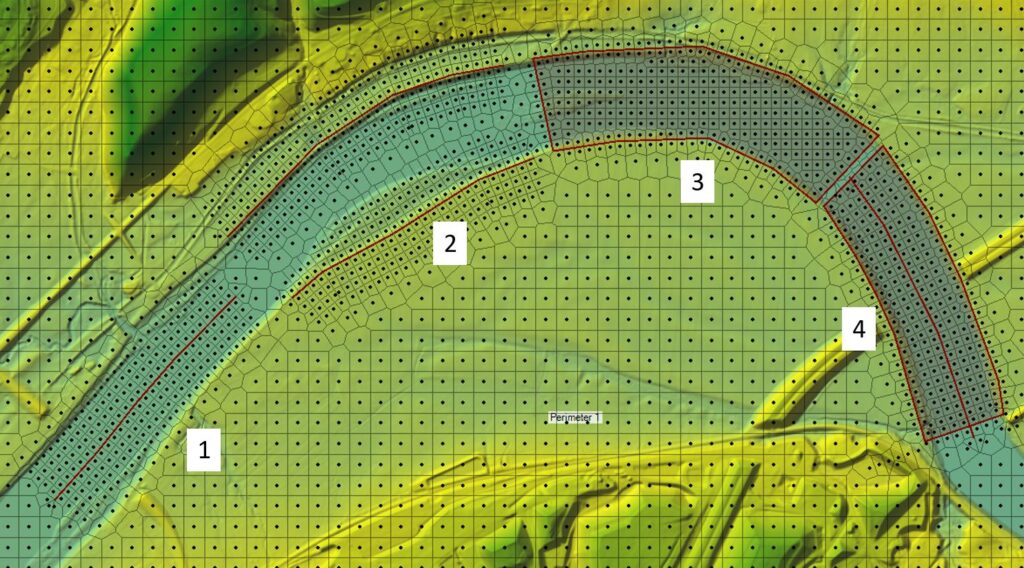
- Centerline Breakline with Near Repeats: use a single breakline digitized directly down the centerline of the river channel. In the breakline properties, a relatively small Near Spacing value is paired with several Near Repeats up to the left/right banks. This method can leave disorganized or jagged cells at the outer edges of the channel where the repeats end so the top of the bank may not be captured adequately.
- Dual Breaklines on the Left and Right Banks with Near Repeats: two breaklines are placed on the left and right to position the cell faces along the top of the banks. Near Repeats are used to push cell rows inward from the banks. Near the river centerline, the repeated cells from the left and right often collide awkwardly, which may result in poorly aligned cells in the center of the river.
- Standard Refinement Region Bounding the Banks: a simple refinement region is drawn around banks of the river to enforce the perimeter cell faces to match the top of the banks. The internal Cell Spacing X and Y are set to a uniformly smaller size than the background mesh. The internal cells maintain a rigid global orientation and do not follow the river flow direction well.
- Centerline Breakline + Refinement Region Bounding the Banks: this is the “Gold Standard” approach that combines the strengths of the other methods. A Refinement Region polygon tracks the outer channel bounds (set to Enforce 1 Cell Protection Radius so any nearby break lines cannot interfere with the already-enforced bounds), while an interior Centerline Breakline with Near Repeats dictates the layout of the internal mesh. This method is labor Intensive which requires manual adjustment of spacing parameters and order of enforcement (for a better result, enforce the refinement region first and then the breakline).
The new Mesh Generation by Arcs and Regions method of HEC-RAS 2025 completely replaced the HEC-RAS 6.X and HEC-RAS 7.0 mesh method (Figure 6).
- Arcs: Draw arcs along channel centerlines, bank lines, high-ground ridges, roadway embankment, or boundary of meshes. An arc can also be used as a breakline if falling inside a region. Cell sizes along arcs can also be defined in arc attributes, different from the region cell size definition.
- Regions: Areas enclosed by arcs. Each region is meshed independently depending on region attributes (cell sizes, cell shapes – Triangular, Cartesian, and Quad).
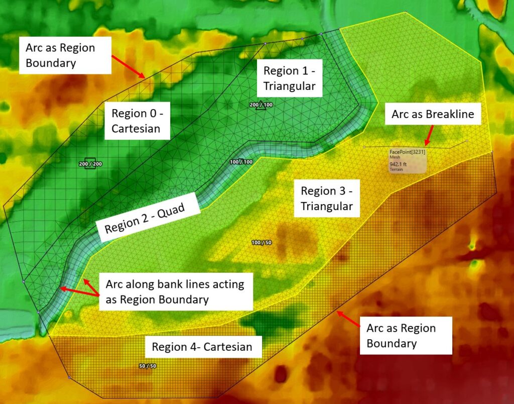
In HEC-RAS 2025, defining a river channel is easier by applying “Quad” cells inside a region bounded by the river banks while the floodplains can be meshed using “Triangular” or “Cartesian” cells as shown in Figure 4.

Leave a Reply