Bridge Scour Analysis By HEC-18 Equations – Contraction Scour (1 of 2)
Bridge scour analysis is often required to design a new bridge or evaluate an existing bridge. Bridge scour depth is a critical bridge design component for foundation calculation. The scouring process happens when more river bed sediments are displaced by moving water than replenished from upstream. When a scour hole gets larger, the water velocity becomes smaller (so does the amount of sediments being removed) until a new balance is reached between sediments being removed and supplemented – at this point, the ultimate scour depth is formed.
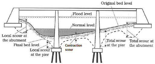
Per FHWA HEC-18, the total scour consists of three primary components (Figure 1):
- Long-term degradation: river bed lowering or scouring over relatively long reaches due to a deficit in sediment supply from upstream.
- Contraction scour (this post and another one): scouring from high velocity due to narrowed river cross sections at the bridge crossing. The contraction scour may be zero if there is no apparent river cross section constriction/contraction by the bridge.
- Local scour at piers or abutments: river bed sediments removal by accelerated flows and resulting vortices introduced by local obstacles such as piers or abutments.
FHWA has adopted a risk-based approach to determine scour design flood frequencies and check flood frequencies (Table 1) since 2010 per HEC-18. Prior to that, all bridges were to be designed for scour by 100-year flows and checked with 500-year flows.

This post is to focus on normal contraction scour (horizontal contraction under non-pressure flow condition) and another post is to explain vertical contraction scour (or pressure flow scour).
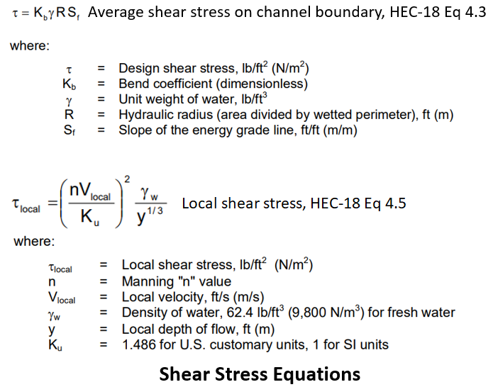
The driving force behind scouring or sediment removal is the shear stress (Figure 2) imposed on a sediment particle by flowing water: when this shear stress is greater than its critical shear stress, scour happens.
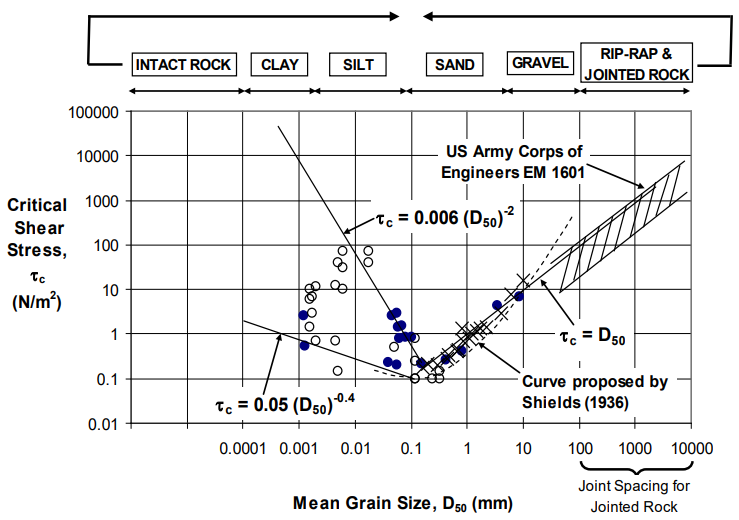
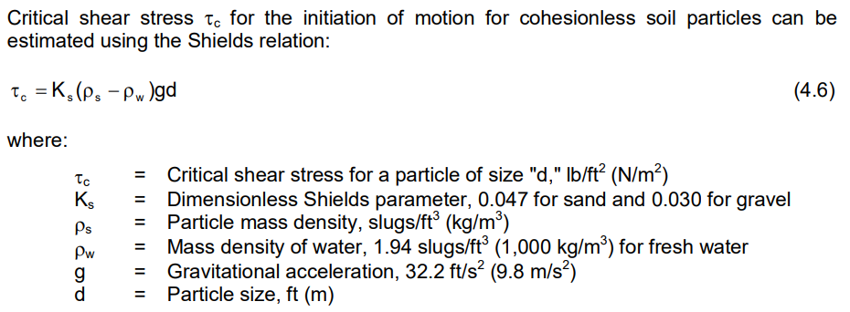
Different sediment particles’ critical shear stresses were measured and summarized in Figure 3, or it can be calculated using appropriate equations in Figure 4. As shown in Figure 3, the relationship between the critical shear stress and the particle grain size is a “V” shape which means that the most erodible sediments are fine sands with a mean grain size in the range of 0.1 to 0.5 mm (or use 0.2 mm as the cutoff value). It is obvious that for cohesionless soils (D50 > 0.2 mm), the larger the grain size, greater the critical shear stress (more difficult to remove sediment particles); while for cohesive soils (D50< 0.2 mm), the smaller the grain size, greater the critical shear stress (more difficult to remove sediment particles) due to the greater cohesive binding forces between finer particles.
Sometimes it is easier to apply the concept of critical velocity instead of critical shear stress for scour analysis, which is illustrated in the cohesionless soil contraction scour equations below.
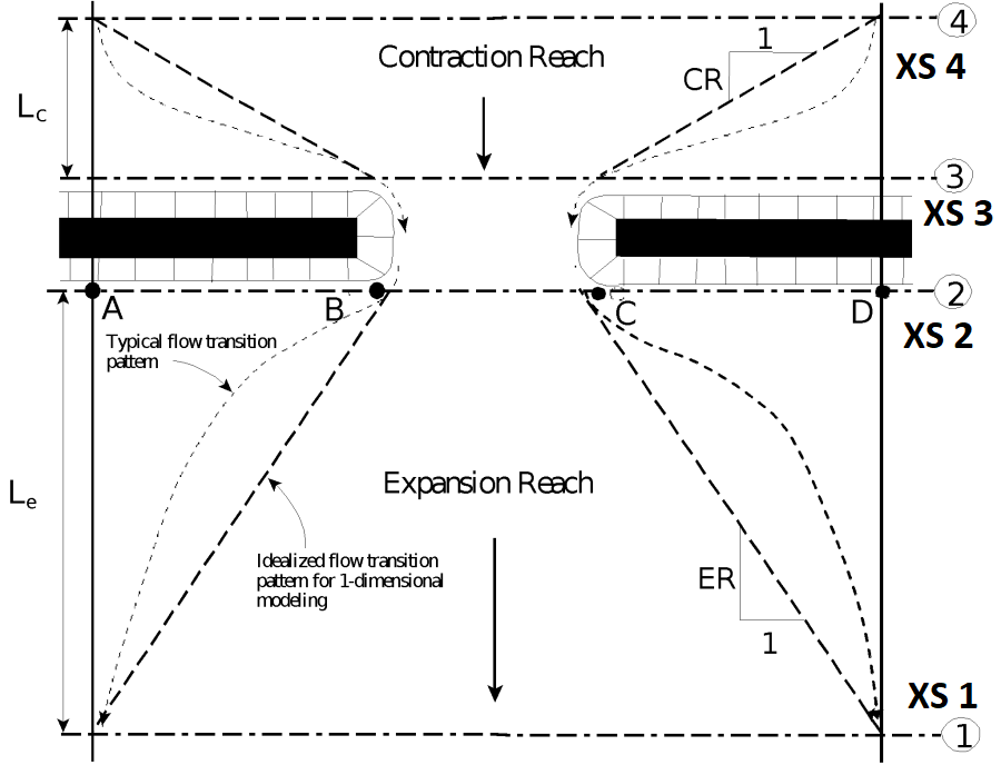
It is a common practice to first set up a steady state bridge hydraulic model in HEC-RAS (Figure 5) under design flows and then utilize the FHWA HEC-18 bridge scour equations coded in HEC-RAS to calculate contraction and local scours.
Contraction scour can happen in cohesionless soil (sand and cobble) and cohesive soil (silt and clay) and these two types of scouring are handled differently in FHWA HEC-18.
Contraction scour – cohesionless soil (noncohesive soil)
Two types of contraction scours in cohesionless soil may occur depending on the bridge approach XS 4 flow velocity and the critical velocity based on D50 (Figure 6).
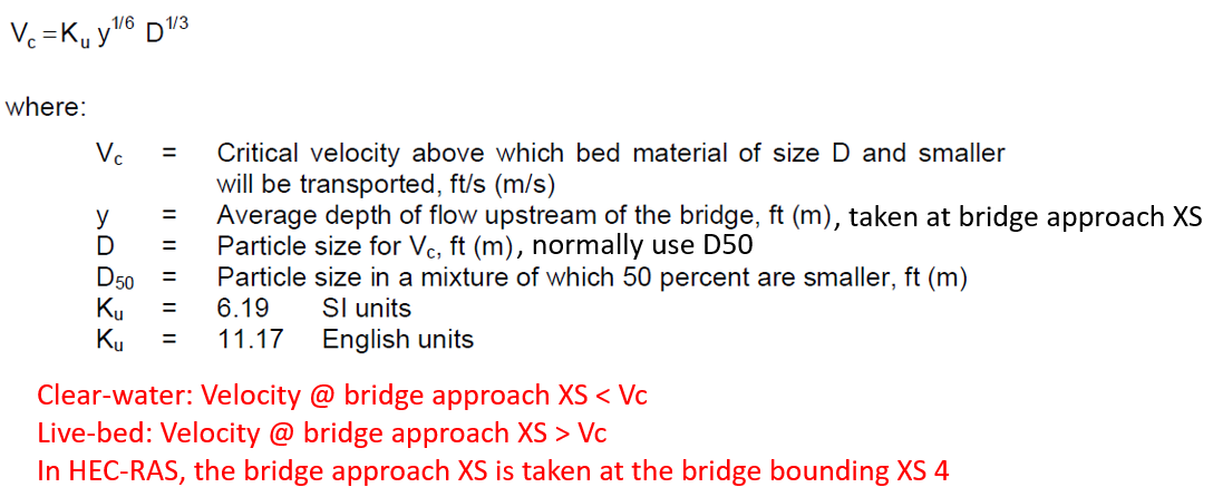
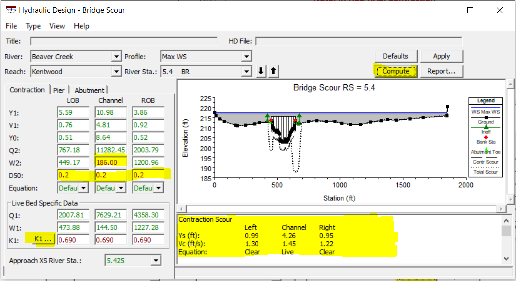
FHWA HEC-18 provides two sets of equations to calculate live-bed contraction scour (HEC-18 Eq 6.2) and clear-water contraction scour (HEC-18 Eq 6.4) and both of them have been coded in HEC-RAS Hydraulic Design – Bridge Scour function (Figure 7 and Figure 8). After a successful steady state bridge hydraulic run under scour design flows, open Hydraulic Design – Bridge Scour to examine the default parameters that are automatically filled in and provide D50 values for LOB, Channel, and ROB in unit of mm. D50 values should come from soil particle gradation test but often in lack of the gradation data engineers assume them to be 0.2mm to get a maximum contraction scour depths for safe design.
Unless there is a setback between top bank of the main channel and the abutments, the contraction scour calculation only needs to be performed for the bridge opening area. In this case, the Q1 is the flow in the main channel of the bridge upstream approach section, not including overbank flows; and Q2 is the total flow going through the bridge opening (see HEC-18 Page 6.10). If an abutment setback exists, the contraction scour can be calculated separately for the main channel and the left and/or right overbank areas using the corresponding HEC-RAS model detailed results (see HEC-18 Appendix D Example).
HEC-18 live-bed contraction scour depth Equation 6.2 coefficient K1 can be calculated by first estimating the D50 fall velocity in reference to HEC-18 Figure 6.8, or using the two fall velocity equations introduced in this post.
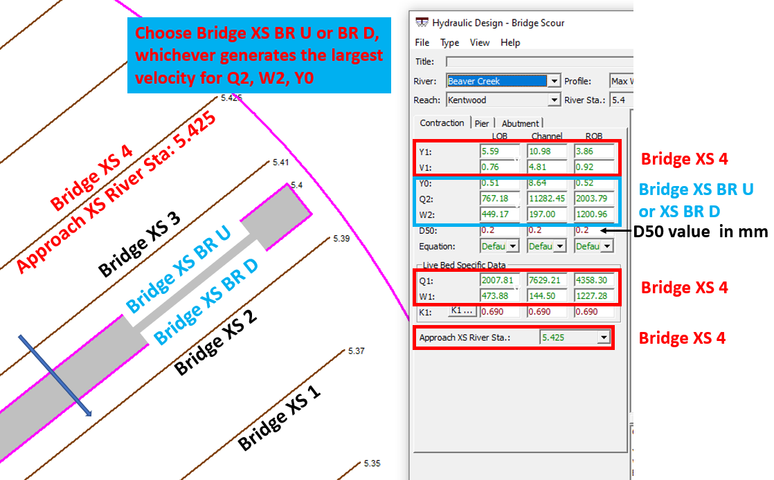
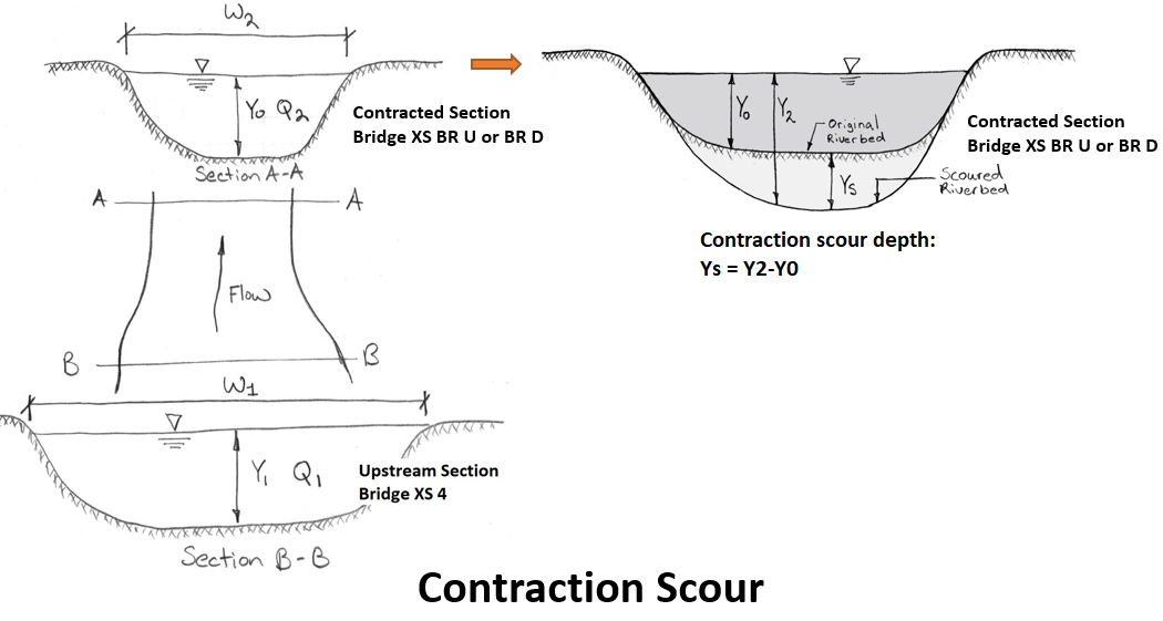
At bridge XS BR U or BR D, by default HEC-RAS automatically adjusts the W2 values by subtracting the bridge pier widths from LOB, Channel, and ROB when the bridge is not overtopped, however, a modeler is encouraged to do a backcheck to ensure W2 values do exclude pier widths. Click “Compute” button and the contraction scour calculation results are shown in Figure 9.
It is important to note that in HEC-18 cohesionless soil scour equations, the user-provided D50 should never be less than 0.2 mm.
When the contraction scour is under live-bed condition (V1>Vc), the actual contraction scour depth may be limited by river bed armoring by coarse sediment transportation. HEC-18 suggests that for contraction scour under live-bed condition, when coarse sediments (D50>=20mm per HEC-18 Chapter 7.11) are present, the clear-water scour depth should be calculated as well and the recommended contraction scour depth is the smaller one of the two.
It is highly recommended to calculate bridge scour depths outside HEC-RAS (for example using a spreadsheet or FHWA Hydraulic Toolbox) since the HEC-18 scour equations in HEC-RAS are not up to date; HEC-RAS bridge scour function should only be used to supply Y, V, Q, W parameters for scour calculations..
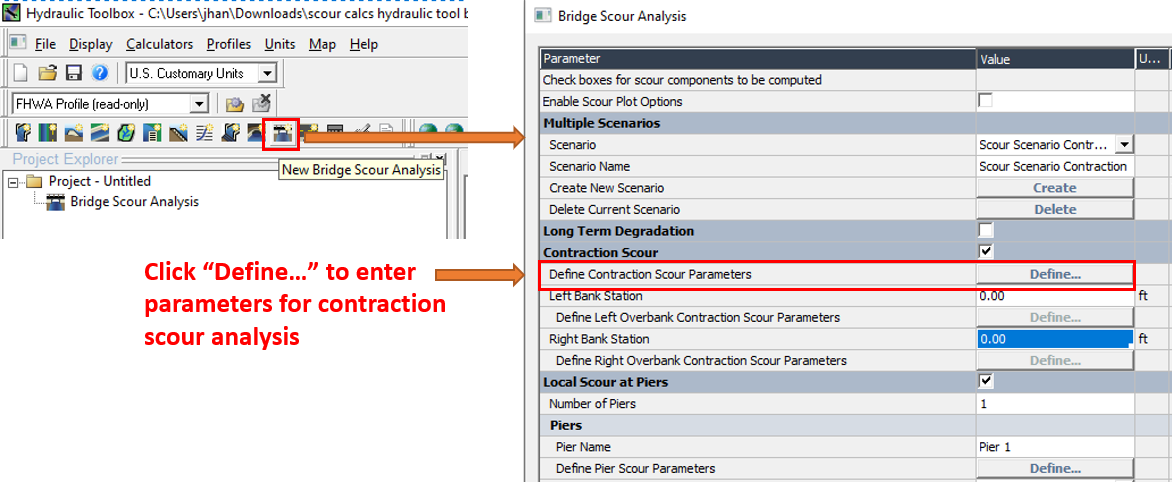
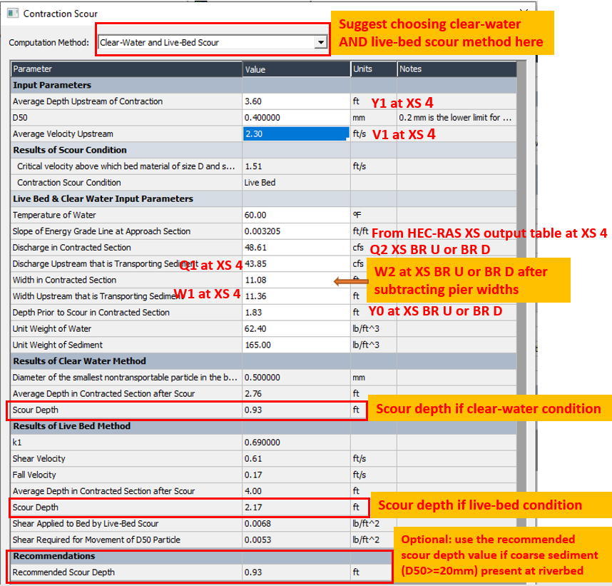
FHWA Hydraulic Toolbox is easy to use for bridge scour analysis (Figure 10 and Figure 11). The Hydraulic Toolbox parameter window is dynamic, which means the optional items or parameters previously selected/entered would determine what items or contents will be displayed next.
Contraction scour – cohesive soil
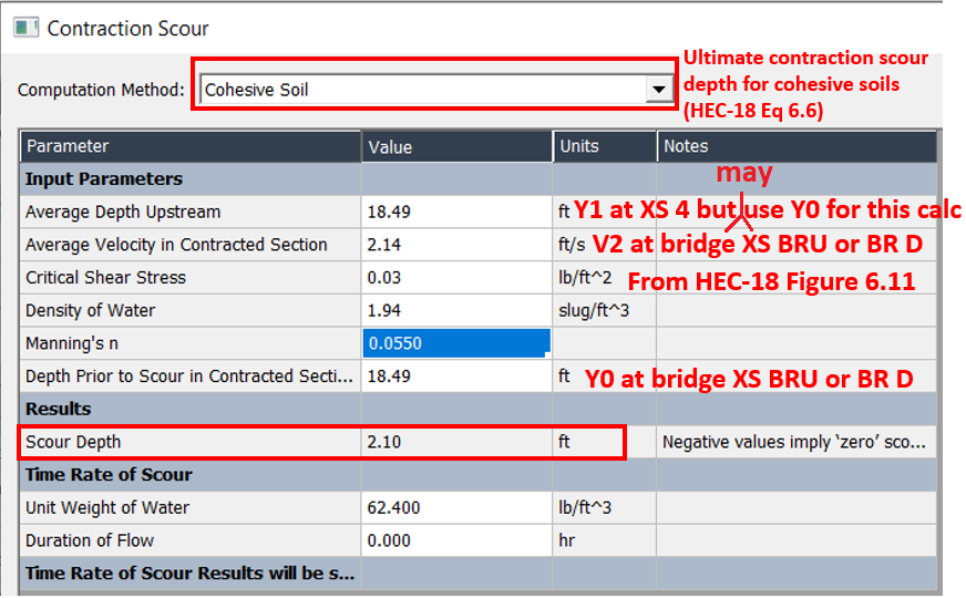
The contraction scour in cohesive soil is more difficult to calculate due to the fact that cohesive soil erosion rate is hard to predict and measure. Briaud developed an equation to calculate the ultimate cohesive soil contraction scour depth (Figure 12, HEC-18 Eq 6.6), which has not been coded into HEC-RAS.
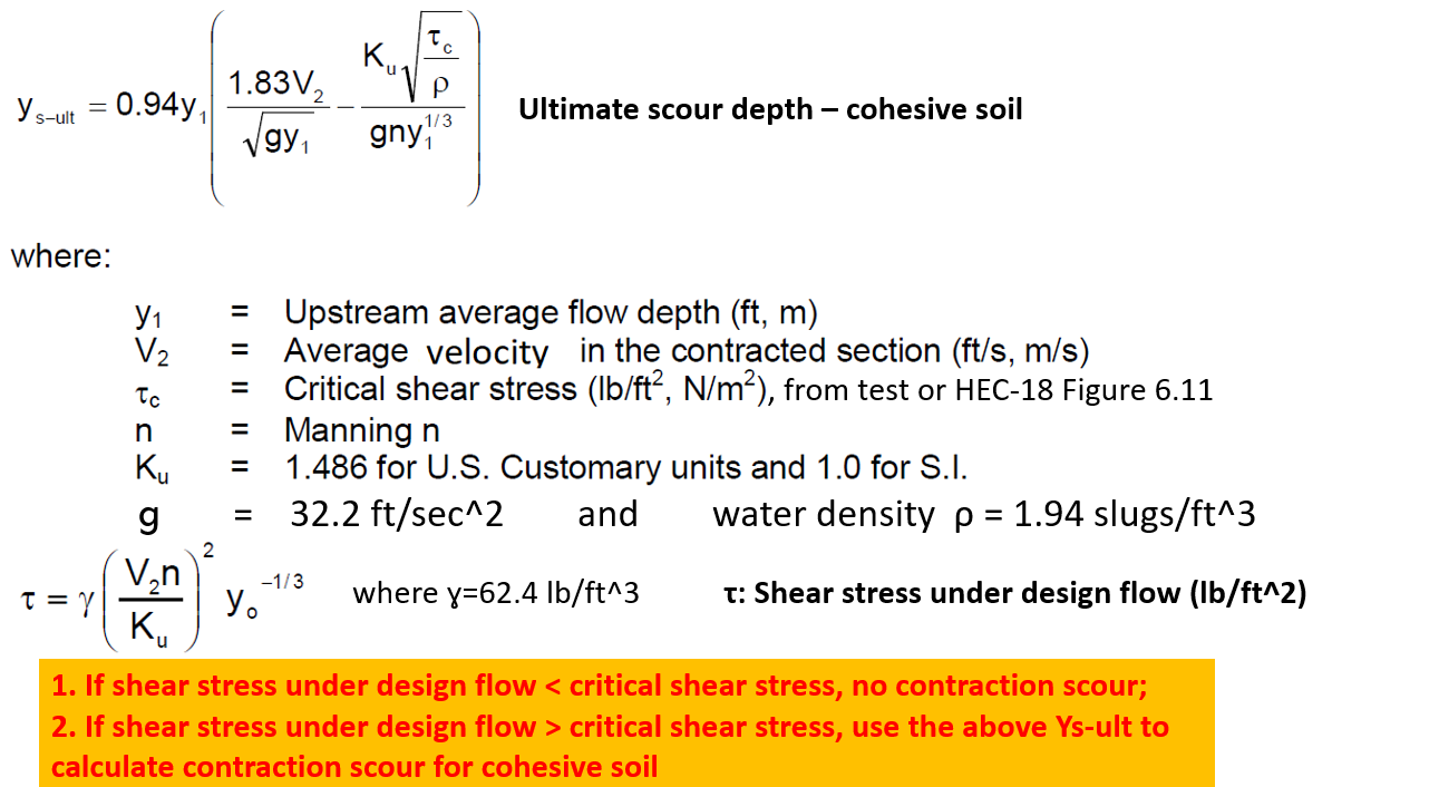
Y1 in the equation above may take the value of Y0 (flow depth in the contracted section) since during the development of the equation it was assumed that the upstream flow depth is equal to the flow depth in the constriction per HEC-18 Page 6.16.
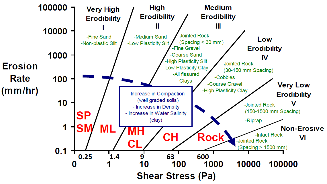
The most difficult parameter to estimate in the equation above is the critical shear stress which has to come from material testing. Briaud generalized the relationship between critical shear stresses and erosion rates as shown in Figure 13 (HEC-18 Figure 6.11). For medium erodibility soil MH or CL, its critical shear stress can be estimate as 1.4 ~ 9 Pa or 0.029 ~ 0.19 lb/ft^2 (1Pa=0.0209 lb/ft^2) by assuming the erosion rate is 0.1 mm/hr; similarly, the low erodibility soil CH has a critical shear stress of 9 ~ 63 Pa or 0.19 ~ 1.32 lb/ft^2 when the erosion rate is 0.1 mm/hr.
FHWA Hydraulic Toolbox has coded in the ultimate contraction scour depth equation for cohesive soils (Figure 14).
As explained above, the ultimate cohesive soil contraction scour depth is difficult to estimate and a material test or an assumptions has to be made in order to apply the equations in Figure 12. For this reason, and also considering the fact that the cohesive soil scour is usually much smaller than the cohesionless soil scour under the same hydraulic conditions, the contraction scour calculation is usually carried out using cohesionless soil scour equations for simplicity and safe design no matte what type of soil is present in the river bed.
In fact, TxDOT Scour Evaluation Guide requires using cohesionless contraction scour equations for cohesive soil condition by assuming D50 to be 0.2 mm (6.56 x 10^-4 ft or 7.87 x 10^-3 in), which will generates a conservative and safe design.
4 COMMENTS