Bridge Scour Analysis By HEC-18 Equations – Local Pier Scour
Bridge scour analysis is often required to design a new bridge or evaluate an existing bridge. Bridge scour depth is a critical bridge design component for foundation calculation. The scouring process happens when more river bed sediments are displaced by moving water than replenished from upstream. When a scour hole gets larger, the water velocity becomes smaller (so does the amount of sediments being removed) until a balance is reached between sediments being removed and supplemented – at this point, the ultimate scour depth is formed. This post is to focus on local pier scour while another post is for contraction scour.
Pier scour – cohesionless soil
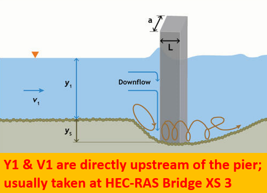
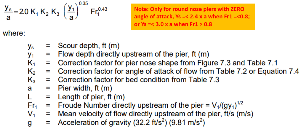
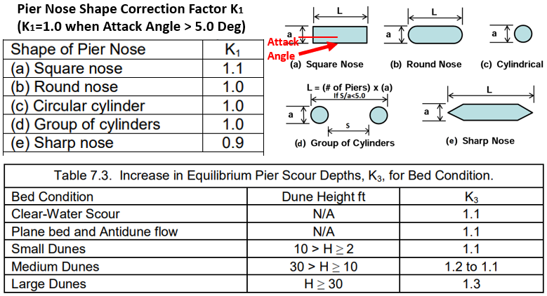
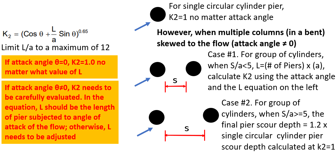
Per FHWA HEC-18, local scour is due to river bed sediments being removed by accelerated flows and resulting vortices introduced by local obstacles such as piers or abutments (Figure 1). HEC-18 pier scour Equation 7.3 (CSU Equation) is applicable for both live-bed an clear-water conditions in cohesionles soils (Figure 2).
For reach individual pier, a unique V1 and Y1 value can be retrieved from HEC-RAS flow distribution output table of XS 3 (Figure 5A and Figure 5B) for its pier scour depth calculation; or the maximum V1 and its corresponding Y1 can be used for every pier to be conservative or due to channel migration potential.

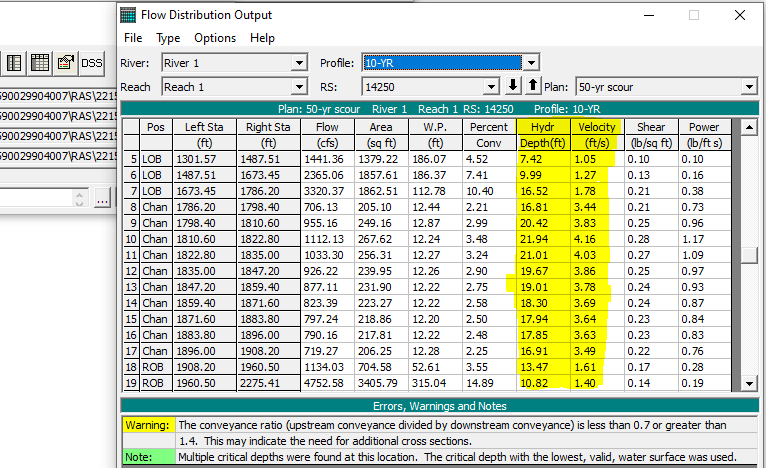
The individual pier’s V1 and Y1 values as well as the maximum V1 Y1 values can also be read directly from HEC-RAS bridge pier scour calculation window (Figure 5C).
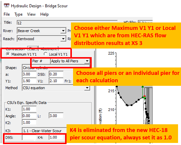
HEC-RAS bridge scour equations are not updated to the newest HEC-18 guidelines and for this reason it is recommended to use FHWA Hydraulic Toolbox or a spreadsheet for bridge scour calculation with input parameters coming from HEC-RAS bridge modeling results.
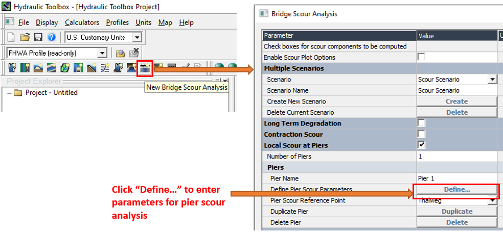
FHWA hydraulic Toolbox is easy to use for bridge scour analysis (Figure 6). The required parameters can be retrieved from a successful steady state HEC-RAS model run (Figure 7). The Hydraulic Toolbox parameter window is dynamic, which means optional items or parameters previously selected/entered would determine what items or contents will be displayed next.

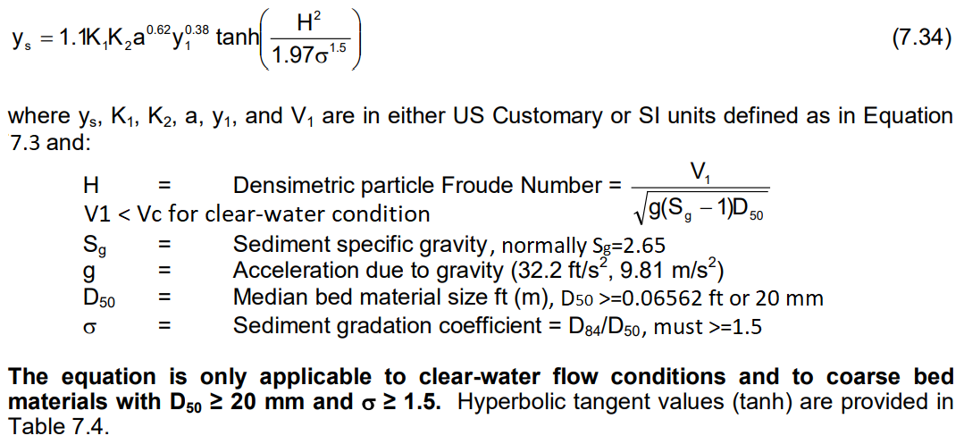
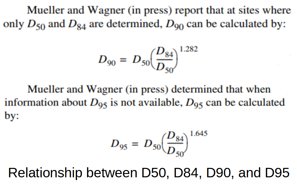
The HEC-18 Edition 5 (2012) dropped a coarse-bed armoring factor (K4) from Equation 7.3, which is why there is no K4 in Figure 2, and instead, proposed another equation for the pier scour depth in coarse material bed under clear-water conditions (Figure 8). This equation is preferred over Equation 7.3 in Figure 2 if the conditions are all met: clear-water, D50>=20mm, D84/D50>=1.5. D50, D84, D90 and D95 relationships can be found in Figure 9.
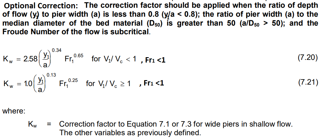
For a wide pier (y1/a<0.8), the pier scour depth Equation 7.3 may be further corrected by engineering judgement via a new wider pier correction factor Kw (Figure 10).
Pier scour – cohesive soil
Pier scour in cohesive soils develops more slowly and is more dependent on soil properties than non-cohesive sediments. Briaud presented an ultimate pier scour depth equation for cohesive soils that incorporates the critical velocity for initiation of erosion (Figure 11, HEC-18 Eq 7.35). The critical velocity for different types of soils can be estimated from Figure 12 (HEC-18 Figure 4.7) by assuming erosion rate of 01. mm/hr. For the medium erodibility soil MH or CL, its critical velocity is between 0.5 ~ 1.4 m/s or 1.6 ~ 4.6 ft/s; similarly the low erodibility soil CH has a critical velocity is between 1.4 ~ 3.6 m/s or 4.6 ~ 11.8 ft/s.


FHWA Hydraulic Toolbox has coded in the ultimate pier scour depth equation for cohesive soils (Figure 13).
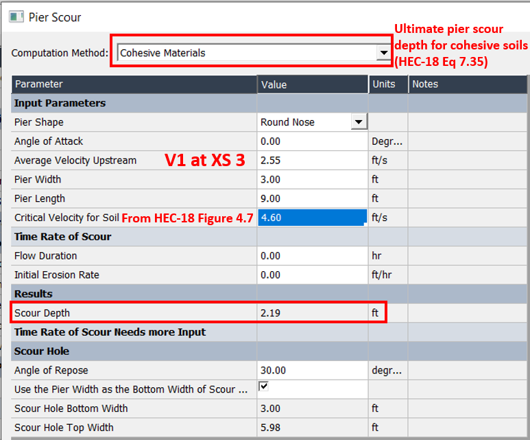
Calculating ultimate pie scour depth for cohesive soils involves uncertainties when determining the soil critical velocity. In engineering practice, this equation is seldom used, and instead, the pier scour depth in cohesive soils is estimated as a certain percentage (for example 50%) of cohesionless soil pier depth from HEC-18 CSU equation in Figure 2.
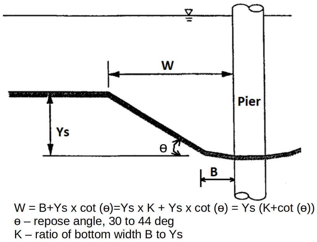
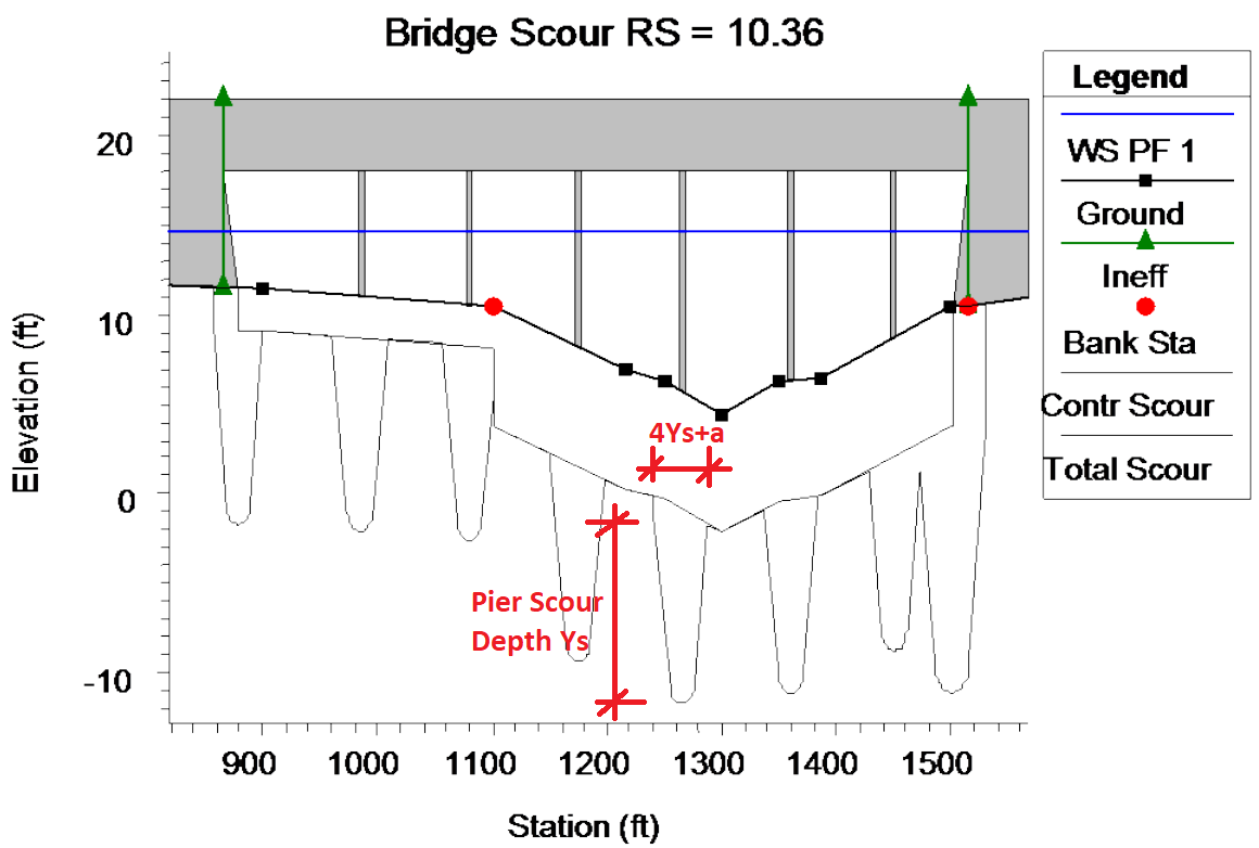
Pier scour hole top width (one side of the pier) can be calculated using equation in Figure 14. For simplicity, HEC-18 suggest using 2.0 x Ys for W in practical applications, which is also how HEC-RAS bridge scour routine handles pier scour hole top widths (Figure 15). Note W is one-side scour hole width and the total top width of the pier scour hole including pier width a is 4.0 x Ys +a in Figure 15.
1 COMMENT