Modeling Reservoir and Dam in 1D HEC-RAS by Storage Area and Inline Structure
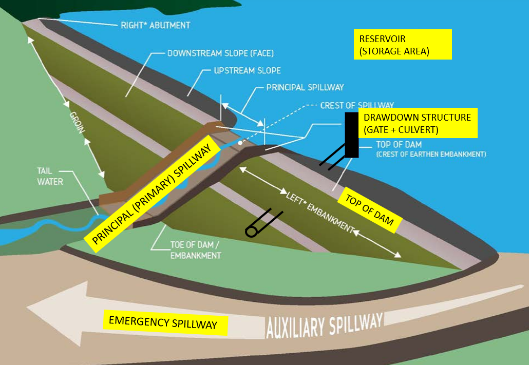
A reservoir is usually built to provide flood control, water supply and irrigation, recreation, or their combinations by blocking a river via embankment dams (Figure 1). A reservoir may have a gated drawdown structure to control pool levels (lower pool level in advance of a major storm event, take in water, or empty reservoir for inspection). A primary (principal) spillway is to provide controlled or uncontrolled water release during big storm events to prevent a dam from being overtopped. Optionally, an emergency spillway can be constructed only to pass the largest and rarest floods. For this reason, erosion damage to dam embankment is expected when an emergency spillway operates under very rare scenarios and this damage is generally acceptable and repairable.
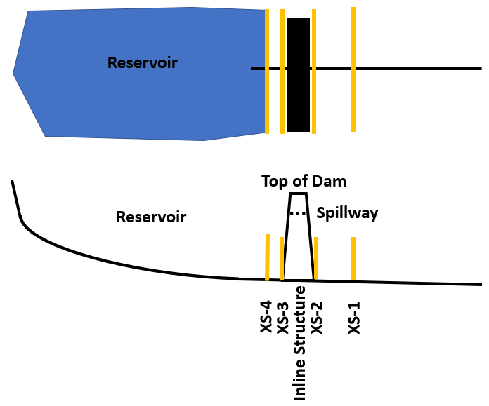
A reservoir can be modeled in 1D HEC-RAS as a storage area with its dam and spillway being modeled as an inline structure. Two cross sections upstream of a dam are needed to model an inline structure (Figure 2) with XS-3 at the toe of the dam and XS-4 being close (10~20 feet away from XS-3). The reservoir Elevation (ft) – Volume (ac-ft) curve data set can be automatically developed by HEC-RAS as explained in this post.
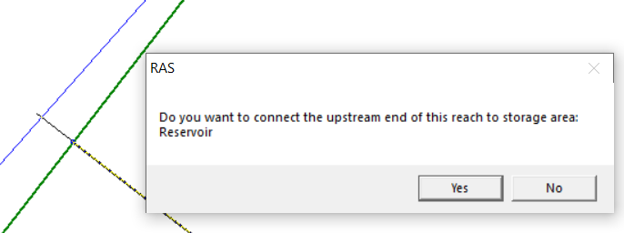
XS-4 is the most upstream cross section of the 1D river and it needs to be connected to the storage area by moving the river reach upstream end point to inside of the storage area (Figure 3). After moving and connecting, XS-4 is tied to the storage area and they always have the same water surface elevations during the computations. It is suggested to start the storage area elevation-volume (cumulative volume) curve with the same elevation as XS-4 invert (the lowest elevation).
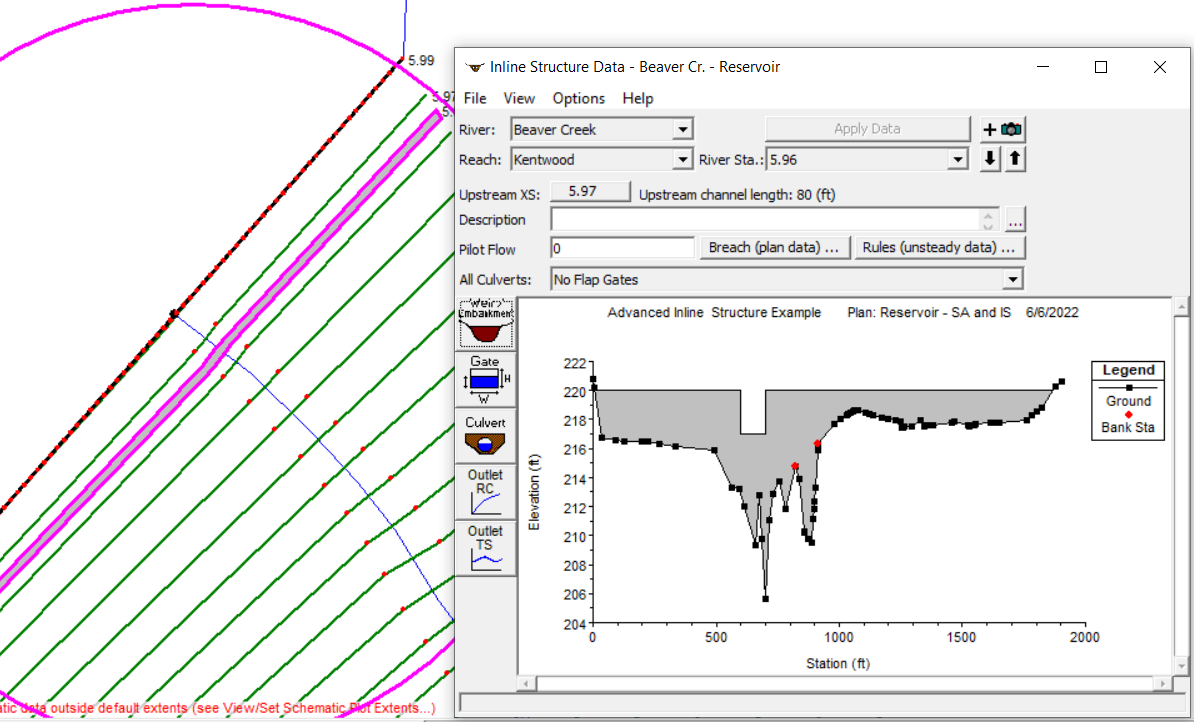
An inline structure is inserted between XS-3 and XS-2 to model the dam, spillway, and gate/culvert if there is any. As shown in Figure 4, the dam and spillway are modeled by entering station-elevation data in Weir/Embankment data editor. Click Gate and Culvert buttons on the left of Inline Structure Data Editor window to add gates and culvert for drawdown structures or other water in-take or release facilities. Other options to model a water release facility include using Outlet Rating Curves (Outlet RC) or Outlet Time Series Curves (Outlet TS)
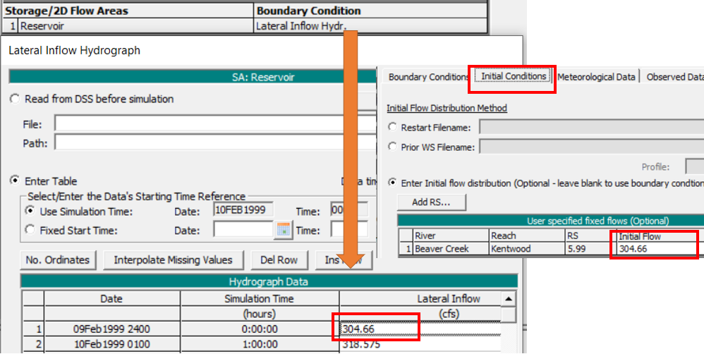
Upstream inflow (or Inflow Design Flood – IDF) should be established as a lateral inflow hydrograph boundary condition for the storage area, instead of the river reach, in Unsteady Flow Data editor (Figure 5). Since XS-4 is connected to the storage area, the outflow will be passed along to XS-4 automatically in a model run. However, it is import that the XS-4 initial condition must be set up appropriately, and otherwise, HEC-RAS could not figure out the initial flow for it. Usually the XS-4 initial condition flow is taken as the same value (or very close to) in the storage area lateral inflow hydrograph at time=0.
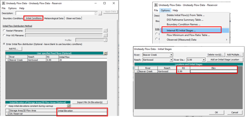
The storage area stage and XS-4 stage are tied together (always same) during a model run. Their initial stage values, however, still need to be carefully set up under Initial Conditions Tab and Internal RS Initial Stages… as shown in Figure 6 (they normally use the same initial stage values).
At the beginning of a model run, HEC-RAS will evaluate all the initial conditions entered by the modeler, or will try to come up with its own values if not provided, to ensure that the initial conditions are in good agreement with each other, for example, the reservoir or XS-4 initial stages must be set up appropriately corresponding to the initial flow values at time=0, otherwise, the model will crash or become unstable very soon. The different initial stage setting strategies are explained below in details. In the following discussions, assume the initial flows for the storage area and XS-4 are entered as the same non-zero value (inflow hydrograph value at time=0) since 1D HEC-RAS river reach can not be run in “dry”.
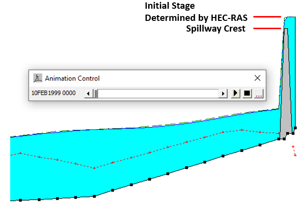
Scenario 1 – Neither the reservoir initial elevation nor XS-4 initial stage is entered and there is also no low flow culvert/gate or pilot flow with the inline structure (dam).
HEC-RAS will try to come up with its own initial stage values for the storage area and XS-4 and these initial stage values will be corresponding to the initial flow. Since there is no other means for the initial flow to be released through the inline structure other than by overtopping the spillway, at time=0, HEC-RAS will automatically fill in the storage area and XS-4 and X-3 to an elevation above the spillway crest to release the initial flows as determined by weir equations (Figure 7).
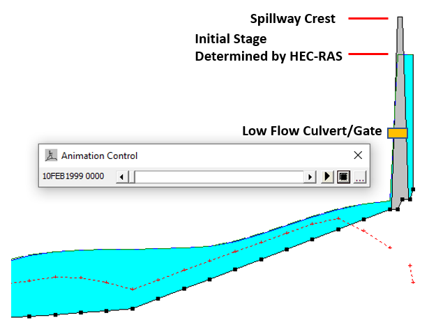
Scenario 2 – Neither the reservoir initial elevation nor XS-4 initial stage is entered but there is a low flow culvert/gate in the inline structure (dam).
Similar to Scenario 1, HEC-RAS will try to come up with its own initial stage values for the storage area and XS-4 and these initial stage values will be corresponding to the initial flow, however, since there is a low flow culvert/gate (invert is lower than spillway crest) in addition to the spillway, at time=0, HEC-RAS will will automatically fill in the storage area and XS-4 and X-3 to an elevation so the flow released through the inline structure is equal to the initial flow. The released flow at time=0 from the inline structure can be culvert/gate flow alone or a combination of culvert/gate flow and spillway weir flow (Figure 8).
Scenario 3 – Set the reservoir initial elevation and XS-4 initial stage as the same value of a desired starting water surface elevation, and at the same time provide a pilot flow for the inline structure (dam).
A pilot flow is an artificial flow introduced to an inline structure to be used as a minimum flow released from the structure (Figure 9). If the hydraulically calculated outflow of an inline structure is larger than the assigned pilot flow, the actual released flow is the calculated outflow; on the other hand, if the calculated outflow is less than the assigned pilot flow, the release flow will take the value of the pilot flow (Figure 10).
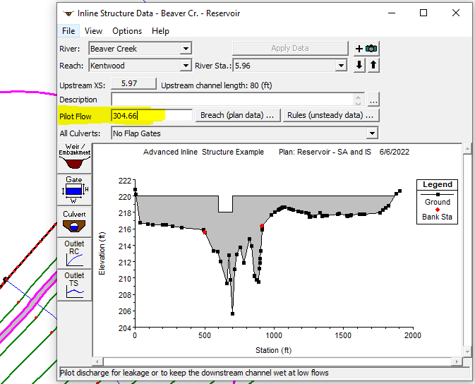
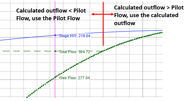
The pilot flow option is a easy way (the other option may be to set up a low flow culvert/gate) to ensure that there are always some flows being released from the inline structure. The value of the pilot flow should be equal to or less than the reservoir initial condition flow.
The reservoir initial elevation and XS-4 initial stage are to be entered as shown in Figure 6 and they should share the same value as the preferred starting reservoir pool elevation. Occasionally a preferred initial pool elevation may not work with the assigned pilot flow value (model to crash or become unstable) and in this case, either of them or both have to be tweaked to make the model run stably.
Here is a summary of the above discussion on how to model a reservoir and dam in 1D HEC-RAS:
- XS-4 and XS-3 are located at upstream of the inline structure/dam and they should be close to each other (10~20ft away)
- XS-4 is tied to the reservoir/storage area and they should have the same initial condition flow and stage. The reservoir elevation-volume (cumulative) curve should start from the invert of XS-4 (the lowest elevation).
- The initial condition stages of the reservoir and XS-4 can be left blank – refer to Scenario 1 and 2 for how HEC-RAS automatically calculates a start water surface elevation for both.
- The pilot flow option allows a reservoir to start from a preferred pool water surface elevation and it serves as a minimum flow to be released from the inline structure during a model run.
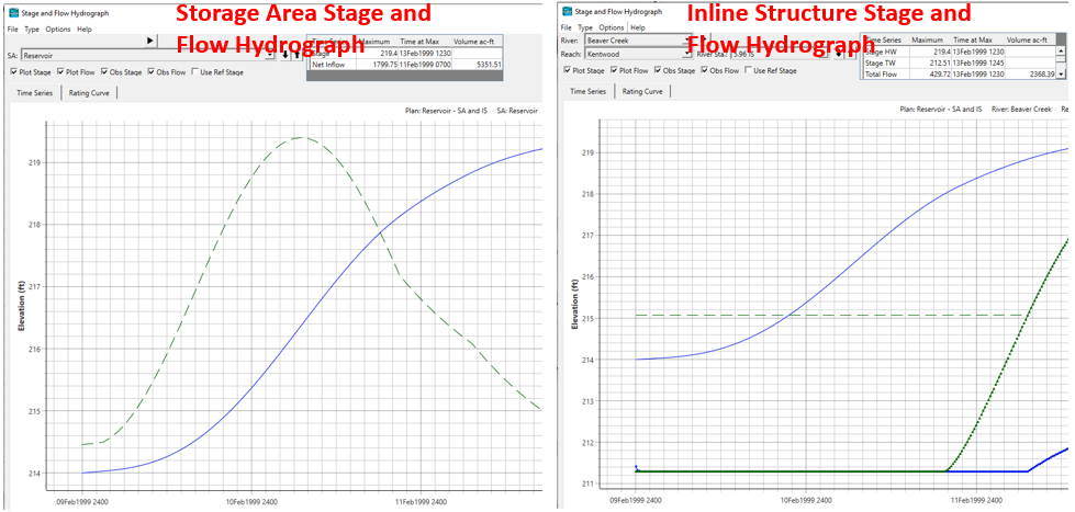
- It is always a good practice to review the stage and flow hydrographs of the storage area, inline structure, or even cross section to ensure that they are operating as expected (Figure 11).
To model a dam breach or dam break analysis in HEC-RAS, refer to this post.
2 COMMENTS