Design A Detention Basin Using Modified Rational Method in HydroCAD (2 of 2)
After a detention basin (a pond in HydoCAD) is added to the model and its storage is defined as explained in here, the next step is to model and design the outflow control structures. An outflow control structure can be as simple as a culvert or a more sophisticated one like the ones shown in Figure 1.
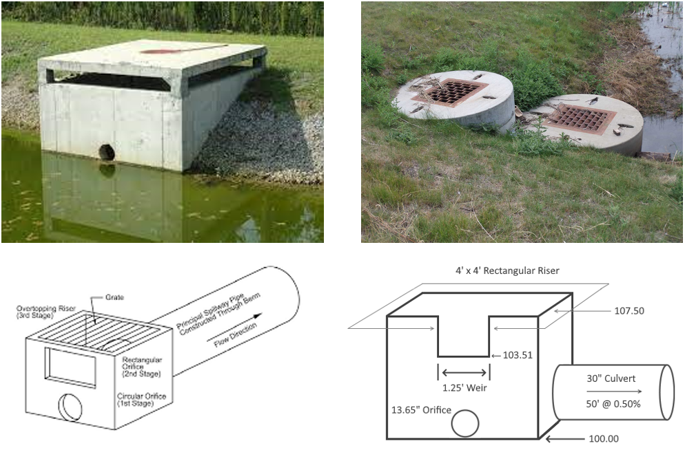
In this example, the proposed outflow control structure is a group of culvert, orifices and weir as shown in Figure 2. The design purpose is to regulate storm water discharges from the detention basin under 2-yr, 10-yr, and 100-yr storm events separately as required by the local codes.
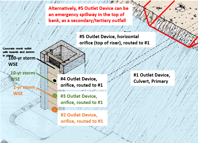
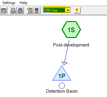
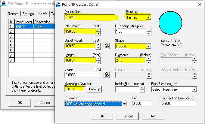
The #1 outlet device is a culvert that routes flow to the pond’s primary receiving waterbody. Make sure the rainfall event selector is set to 100-yr (Figure 3), and by trial and error, the culvert is determined to be a 100ft long 24 inch pipe with an invert matching the basin bottom elevation (Figure 4). The peak outflow rate of 100-yr is 20.50 cfs and its state peak elevation is 193.32. The peak outflow rate of 20.50 cfs is greater than the maximum allowable 100-yr flow rate of 16.14 cfs, which is desired and expected for now since later on new orifices are to be added to further restrict the outflow rates.
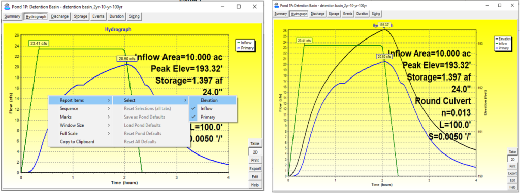
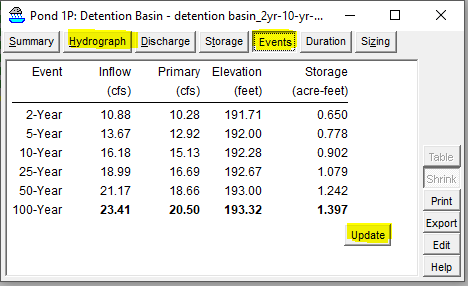
The basin performance under other frequency storms can be viewed by switching from the “Hydrograph” tab to the “Events” tab and then clicking the button of “Update” (Figure 6) so yo don’t need to go back to the rainfall event selector (Figure 3) to re-run the model.
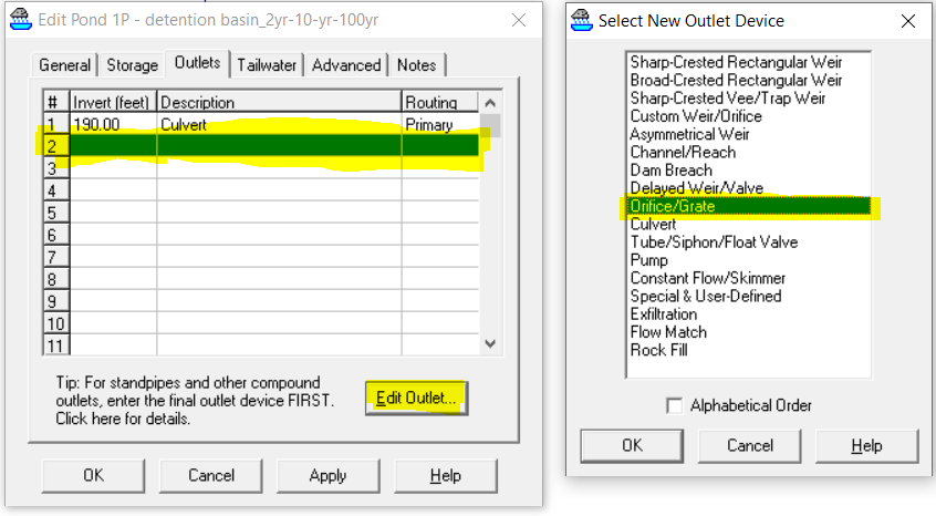
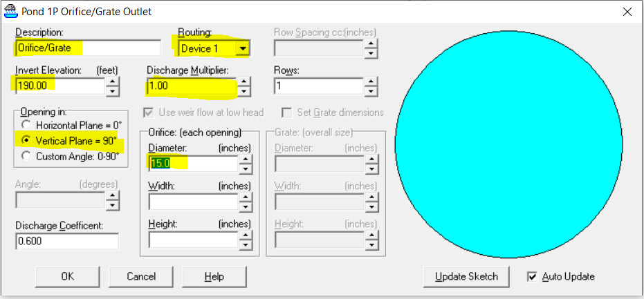
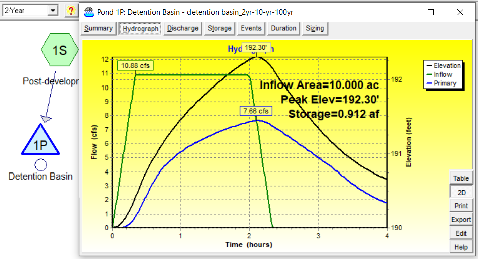
Add an orifice at the basin bottom as #2 outlet device to control 2-yr flow by clicking “Edit Outlet …” when #2 row is highlighted in blue (Figure 7). Ensure the rainfall event selector is set as 2-yr and its routing destination is Device 1 – the 24 inch culvert designed previously. Through iterative model runs, the #2 outlet device is settled down to be a 15 inch diameter circular orifice (Figure 8) and the peak outflow rate of 7.66 cfs is just less than the maximum allowable 2-yr outflow rate of 7.95 cfs (Figure 9).
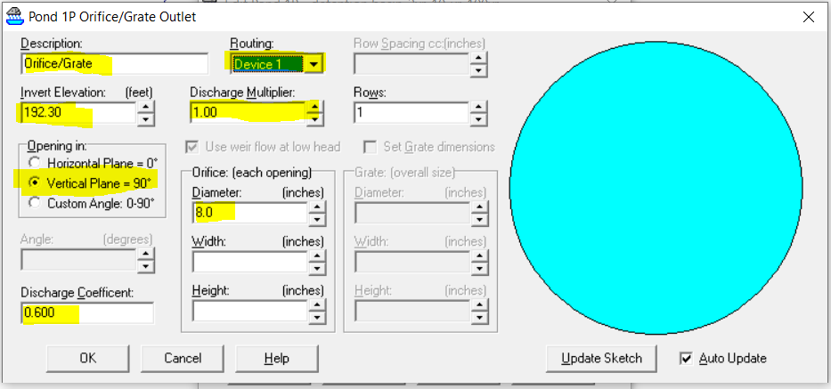
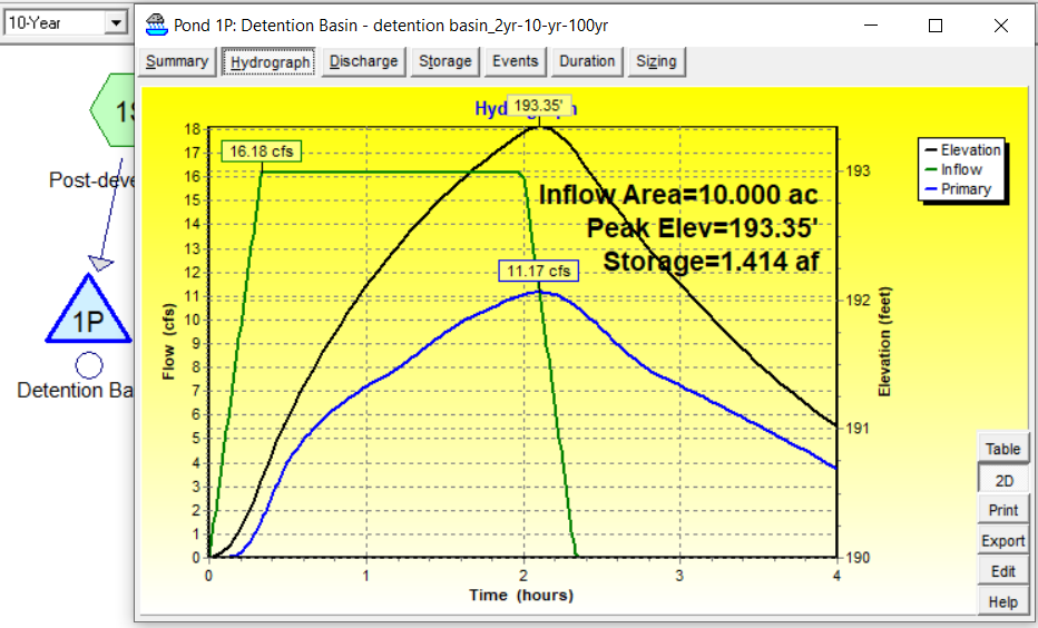
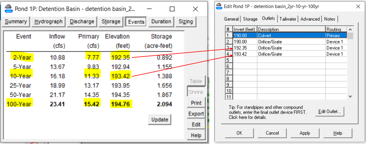
Now move on to #3 outlet device by anther orifice to control 10-yr outflow. The process is similar to the steps above but the #3 outlet device orifice invert should be set at the 2-yr peak stage elevation of 192.30ft (Figure 10). The final diameter of the 10-yr orifice is 8.0 inch and the peak outflow rate of 11.17 cfs is less than the maximum allowable 10-yr outflow rate of 11.42 cfs (Figure 11).
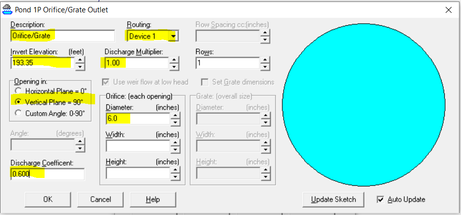
Add #4 outlet device, the 100-yr flow control orifice, at the invert elevation of 193.35ft (10-yr peak stage elevation) (Figure 12). After trial and error, the #4 outlet device diameter is finalized to be 6.0 inch and the peak outflow rate of 15.22 cfs is less than the maximum allowable 100-yr outflow rate of 16.14 cfs (Figure 13)
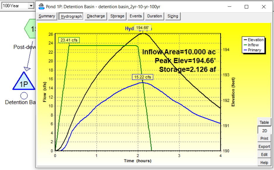
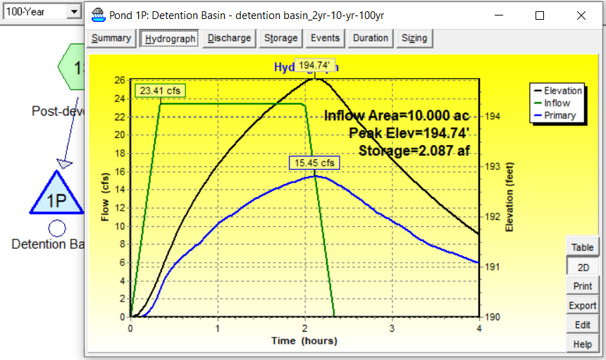
According to Figure 13, the peak stage elevation is 194.66ft which is 0.34 ft short of the 100-yr design stage elevation of 195.0ft, which is an indication that the detention basin storage volume is not fully utilized and thus the basin size can be further decreased. To do so, reduce the detention basin bottom side length to 119.0ft and re-run the model under 100-yr storm. The updated result is shown in Figure 14, from which we can tell that the peak outflow rate of 15.45 cfs is still less than the maximum allowable 100-yr outflow rate of 16.14 cfs but the available detention basin volume is better utilized with the peak stage elevation at 194.74ft.
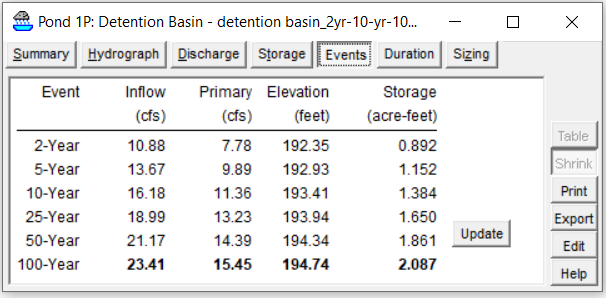
The detention basin performance with the reduced volume under 2-yr and 10-yr storm events can be checked by switching to the “Events” tab and clicking the button of “Update” (Figure 15). Due to the detention volume change, the 10-yr peak stage elevation is higher than its previous value and correspondingly the 100-yr orifice (#4 outlet device) invert has to be raised to match it.
The above process is an iterative one and several rounds of model runs have to be conducted to achieve an optimized detention basin design. The final results of the four outlet devices are shown in Figure 16.
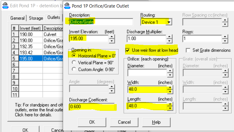
The top of riser (Figure 2) can be modeled as a horizontal orifice structure (#5 outlet device) to safely release excessive storm water from events larger than 100-yr. The horizontal orifice invert elevation is set to be at 195.0ft which is the maximum basin design elevation 196.0ft minus 1.0ft freeboard. Because the horizontal orifice invert is higher than the peak stage elevation of a 100-yr storm, this orifice has no impact on the basin performance for events up to 100-yr. It is important to check on the option of Use weir flow at low head for a horizontal orifice as shown in Figure 17.
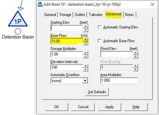
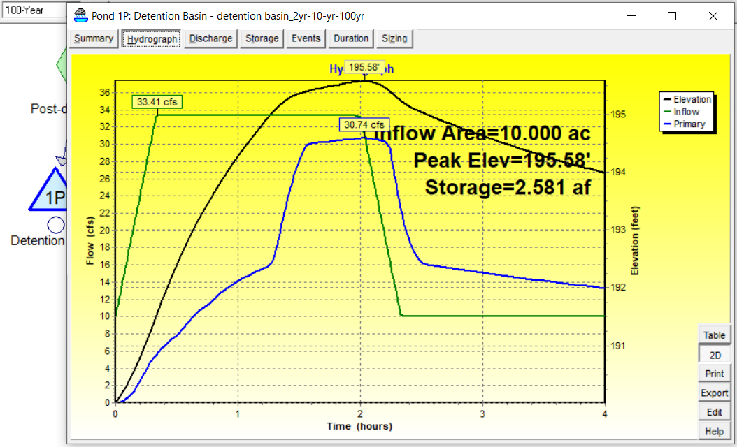
To simulate an event larger than 100-yr to examine the operation of the horizontal orifice, simply add a base flow of 10 cfs to the basin (Figure 18). The result hydrograph in Figure 19 shows that with the additional flow, the peak stage elevation is 195.58ft which is still lower than the maximum basin design elevation of 196.0ft.
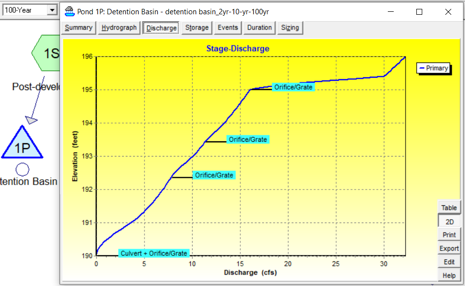
The stage-discharge relationship of the detention basin can be viewed by switching to the “Discharge” tab from the “Hydrograph” tab (Figure 20).
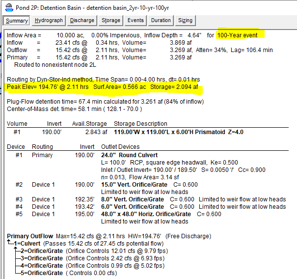
The “Summary” tab, to the left of the “Hydrograph” tab should always be visited to review the summary report and make sure the results presented there are reasonable. As shown in Figure 21, all the critical modeling results can be examined. It is interesting to note that the storage is 2.094 ac-ft at 100-yr peak elevation of 194.76ft, which is less than the preliminary value of 2.3132 ac-ft. This is not surprising since the preliminary basin volume estimation is based on a sloped straight line while in reality the outflow hydrograph is convex.
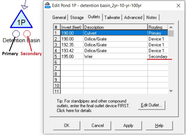
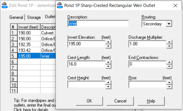
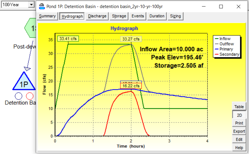
If a different design from what’s shown in Figure 2 is preferred, for example, the excessive flow is to be released from an emergency spillway (the riser top opening is capped) to a secondary or a third/tertiary receiving waterbody, the weir can be added to the model to replace the horizontal orifice (Figure 22 and Figure 23) and the new hydrograph is shown in Figure 24.
The finished detention basin model can be downloaded here.
Leave a Reply