Design A Detention Basin Using Modified Rational Method in HydroCAD (1 of 2)
A storm water detention basin is usually required for a public or private development project to temporarily store excessive post-development runoff and only release the detained water through control structures to ensure post-development peak flows are no greater than pre-development peak flows under the required frequency storms such as 2-yr, 10-yr, and/or 100-yr.
It should be noted that the final detention volume is tied to the actual basin outflow rate – if the actual basin outflow rate is much lower than the Pre-project peak discharge, the corresponding detention volume needs to be larger than the shaded area in Figure 1. For this reason, when designing a detention pond using a fixed detention rate method or Pre-/Post-project hydrograph difference method without routing the Post-project hydrograph in a H&H model, the outflow structure shall be designed in a way that its peak outflow rate matches or slightly lower than the Pre-project peak discharge.
It is recommended to always design a detention pond by routing a Post-project hydrograph in a H&H model which includes the proposed basin and outflow structure geometries, particularly for a large project area.
Six basic steps to size and design a detention basin are:
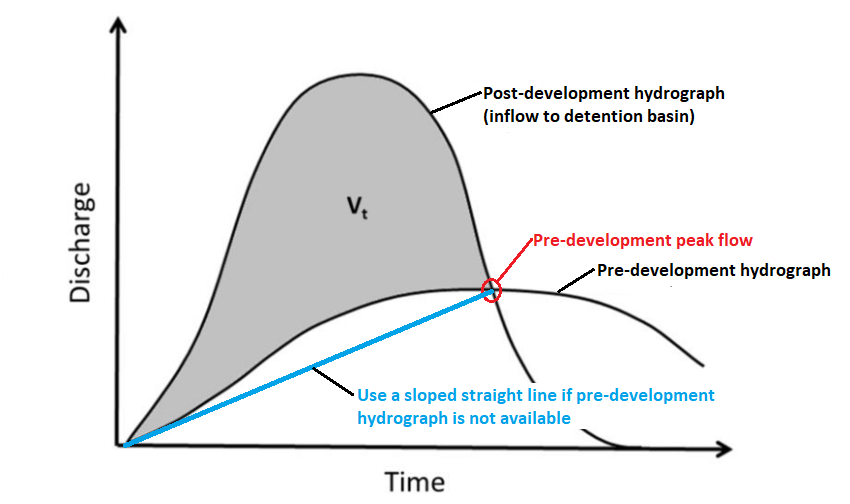
1. Develop pre-development peak flows (hydrographs are optional) and post-development hydrographs under the regulated frequency storms. The pre-development peak flows are to be used as upper limits of allowable discharges from the detention basin, and the post-development hydrographs are inflow hydrographs;
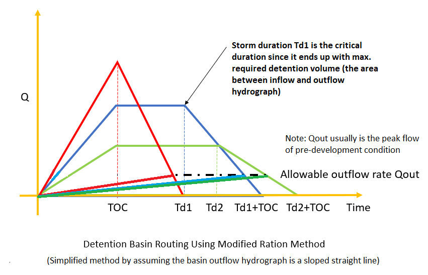
2. Estimate the required detention basin volume which is the shaded area in Figure 1. The estimated basin volume is a preliminary value which can be fine-tuned later;
3. Determine the detention basin geometries (depth, bottom sizes, side slopes, freeboard) and develop its storage curve (elevation – surface area, or elevation – incremental/cumulative storage volume). Type in the storage curve in the detention basin model;
4. Design and model one or more outflow control structures to meet storm water regulation requirements – post-development peak flows are no greater than pre-development peak flows; This is a trial and error process;
5. Design an emergency spillway which usually is a weir structure to safely release storm water runoff from extreme events such as 200-yr or 500-yr;
6. You may want to re-visit step 2 to step 5 to fine-tune the detention basin geometries and outflow control structures to make sure:
- the storage volume is fully utilized under the design storms
- at the same time the freeboard and maximum allowable discharge requirements are still met.
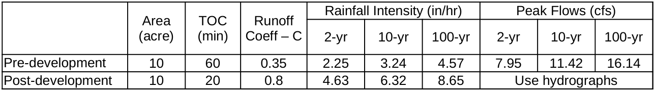
This post is to demonstrate the process of designing a detention basin using HydroCAD. The example is a commercial development project of 10 acres located in Austin County, TX. Its pre-development and post-development site conditions and peak flows are summarized in Table 1. The local storm water regulation requires a detention basin to be designed for a 100-yr storm and control outflows from 2-yr, 10-yr, and 100-yr storm events so the post-development peak flows are no greater than the corresponding pre-development values. The example project uses the Modified Rational Method to develop the required inflow hydrographs, but the theory behind it can be applied to designs using other hydrology methods, such as SCS hydrology.
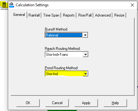
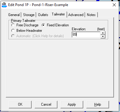
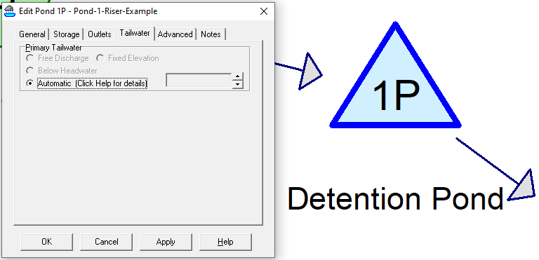
The Modified Rational Method was used to develop the inflow hydrographs, and the steps on how to implement it in HydroCAD are explained in details here. To establish a post-development H&H model in HydroCAD, first click Project–>Open… and enter a new project name to create a new project. Now open the HydroCAD Calculation Settings window by clicking the calculator icon to set up the runoff method (Rational) and reach/pond routing method (Figure 2A). When Pond Routing Method is chosen as Stor-Ind, the pond tailwater may be defined as Free Discharge, Fixed Elevation, or Below Headwater (Figure 2B). In this example, the pond tailwater is assumed to be Free Discharge. It should be noted a free tailwater condition may not be appropriate for certain scenarios and an engineer often needs to refer to local drainage criteria manuals for tailwater requirements. Other acceptable tailwater conditions include fixed tailwater (soffit/top or springline of an outlet pipe, outfall channel WSE of different design frequencies), tidal tailwater, or time-varying tailwater (stage hydrographs). Refer to this post for more details about tailwater conditions.
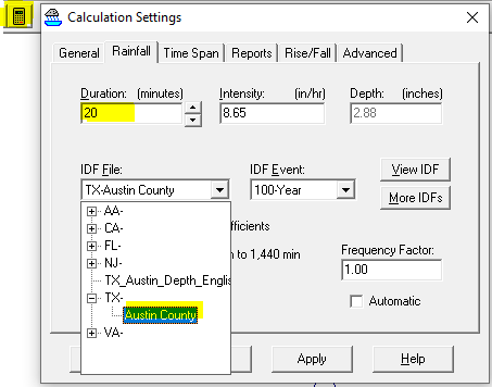
The rainfall duration (determine rainfall intensity) and intensity/IDF are to be provided under the “Rainfall” tab (Figure 3). The intensity can be typed in directly, or it will be automatically filled out based on the duration and the IDF file/event chosen.
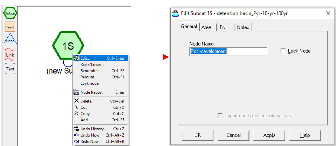
Now drag the green color “Subcat” creation icon to the main window blank area. Right click the “1S” subcatchment node (In HydroCAD any H&H element is called a node, which is different from XPSWMM) to open its data editor window (Figure 4). Rename the “1S” subcatchment as “Post-development” and type in its area, runoff coefficient C, and TOC under each of the tabs – General, Area, and Tc. Click “OK” to close its data editor window.
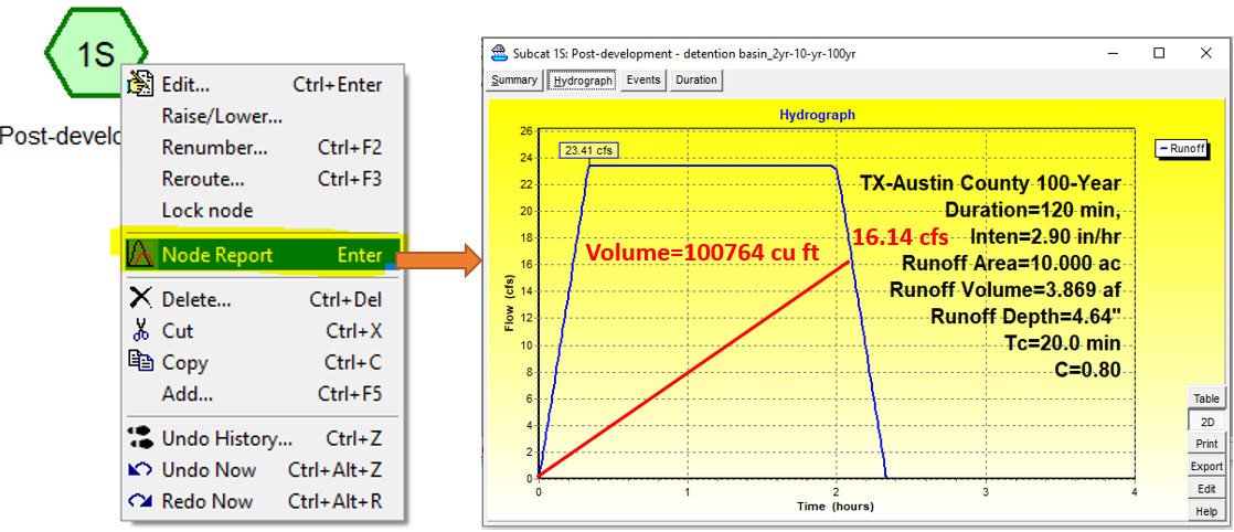
To estimate the the required detention basin volume using modified rational method, run the model by testing different duration time values (20 min, 40 min, …, 120 min, 140 min…) under the 100-yr design storm until the calculated detention volume reaches its maximum (Figure 5). For this example, the maximum volume is 100764 cu ft or 2.3132 ac-ft at duration = 120 min (Figure 6), which is used to size the detention basin geometries.
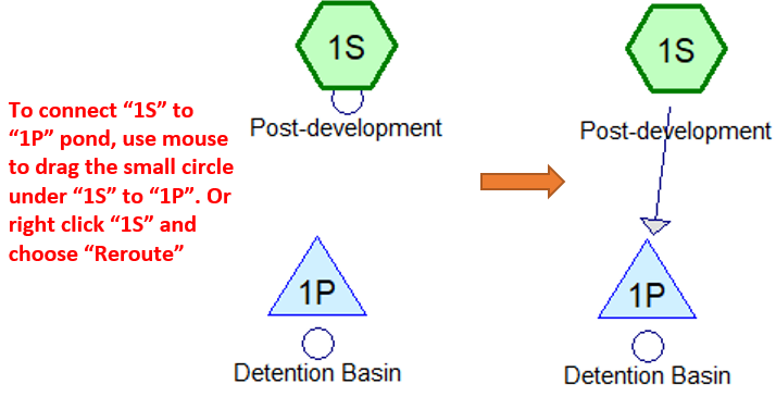
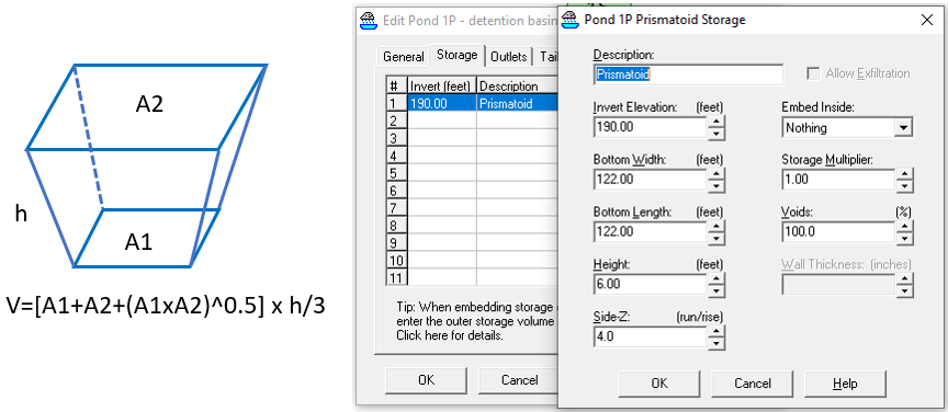
Drag the triangle icon of pond to the main HydoCAD window to add a detention basin to the model and connect “1S” subcatchment to “1P” pond (Figure 7). Assume the proposed detention basin is to be 6.0ft deep including 1.0ft freeboard and its bottom is at elevation 190.00ft. The required detention basin bottom (square shape) side length is about 122.0ft to provide 100764 cu ft volume from elevation 190.0ft to 195.0ft. For preliminary design purpose, the detention basin can take the shape of a prismatoid and its storage relationship can be defined as such (Figure 8). You may also use “custom stage data” to define the detention basin if that’s what you prefer.
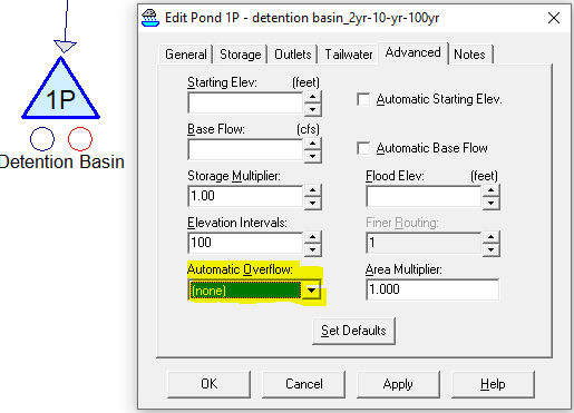
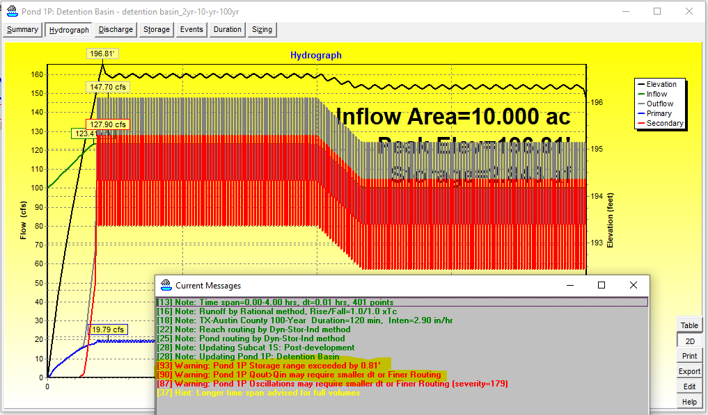
HydroCAD does not extrapolate storage above what is defined at maximum height or elevation. By default, a basin’s overflow option is set as “none” under the “Advanced” tab (Figure 9), and if there is a “net” inflow after the basin has reached its maximum defined storage, the basin will be “pressurized” and behave abnormally with warning messages (Figure 10). Usually it is not a desired scenario for a detention basin to be pressurized unless it is a closed storage tank/chamber which is supposed to operate under pressure.
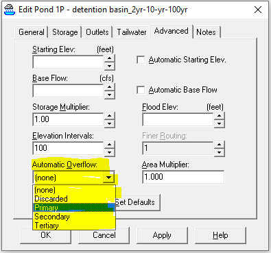
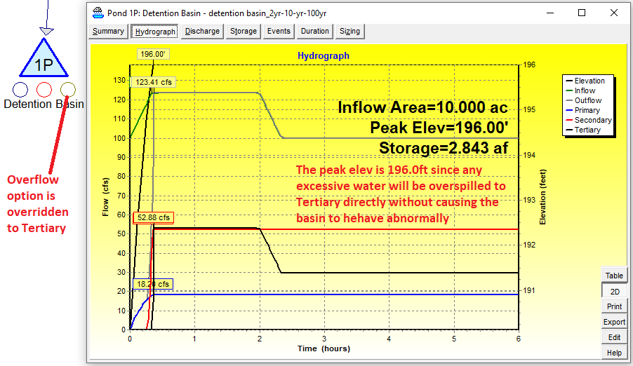
The default overflow option can be overridden to “Discarded“, “Primary“, “Secondary“, or “Tertiary” to prevent the above abnormity from happening (Figure 11 and Figure 12).
The above method is a quick way to resolve the overflow issue in a basin. A better way, when defining the basin storage for the first time, is to set the basin maximum storage elevation/height to a much bigger value than what would be expected (so a much bigger storage volume as well). After several initial runs, the basin maximum storage elevation or height can be reduced to a more reasonable value to reflect the actual field condition. If it is a design feature for a basin to be overtopped under certain extreme storm events, the overtopping flow should be routed through a weir defined as an outlet, and more importantly, the basin maximum storage elevation should be at least set to the expected weir flow headwater elevation by assuming a vertical wall around the basin top banks.
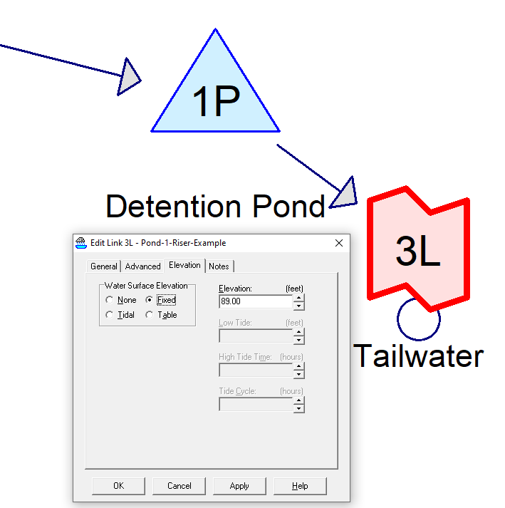
In Figure 2A above, if Pond Routing Method is set as Dyn-Stor-Ind, then the only available pond tailwater option is Automatic as shown in Figure 13. In order to model the tailwater effect, a Link node can be added to the outlet end of the pond which can provide a tailwater condition (Figure 14).
Leave a Reply