HEC-RAS Lateral Structure (1 of 2)
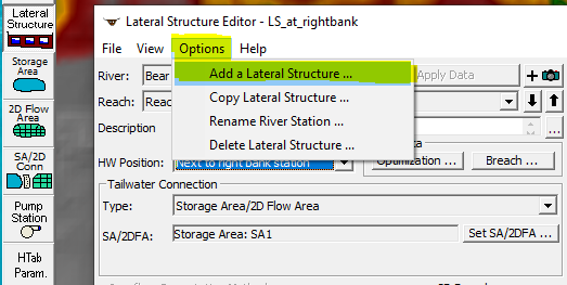
In HEC-RAS models, a lateral structure (LS) is often used to establish a connection between 1D river reach (upstream end of a lateral structure) and a storage area/2D flow area/another 1D river each (downstream end of a lateral structure, or Tailwater) for flow exchanges. A lateral structure is to be added to the model by assigning a river station value slightly smaller than its immediate upstream cross section in HEC-RAS Geometric Data Editor (Figure 1).
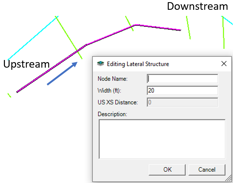
A lateral structure can also be added by using “Add New Feature” tool in RAS mapper by drawing its alignment along the edges of cross sections from upsteram to downstream (Figure 2).
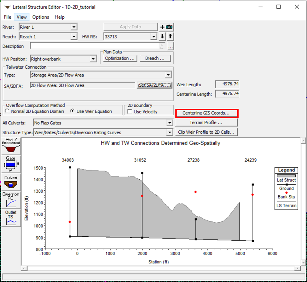
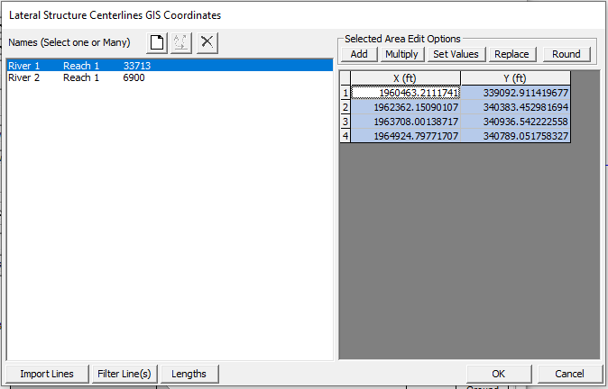
The detail settings of a lateral Structure need to be completed in the Lateral Structure Editor (Figure 3). It is desired (sometimes required) to geo-reference a lateral structure by defining its alignment coordinates as shown in Figure 4. It is a rule of thumb that lateral structures run on top of the high grounds in between river cross sections and storage areas/2D flow areas.
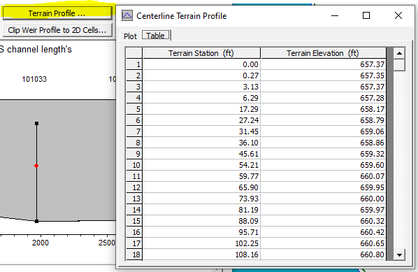
If the weir embankment elevations are to be taken from ground of the associated terrain, click the Terrain Profile button to copy the Table in Figure 5 to the weir/embankment station/elevation table. Whenever a survey is performed for a lateral structure, the weir/embankment elevations should use the surveyed data, which generally has better quality than the terrain ground surface from LiDAR. For man-made lateral structures such as a levee, a spillway, or a diversion weir, elevations read from as-builts can be applied in lieu of the terrain ground surface.
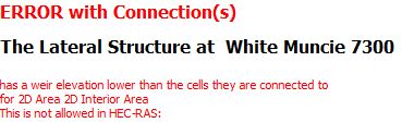
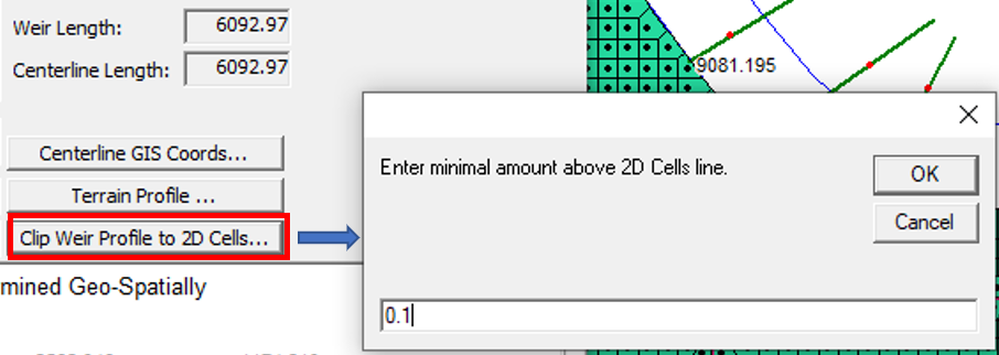
If at any point the weir elevation of a lateral structure is lower than the 2D cell center that it is connected to, HEC-RAS will stop running with an error message (Figure 6). To fix it, a modeler can either re-align the lateral structure, or utilize the Lateral Structure Editor built-in feature of “Clip Weir Profile to 2D Cells…” (Figure 7A) to raise the weir by a minimum amount entered.
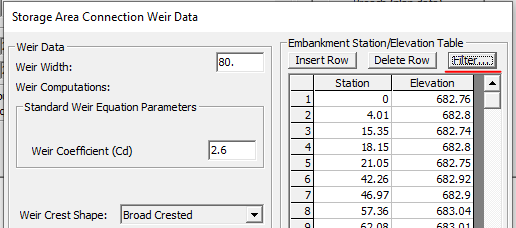
Before applying “Clip Weir Profile to 2D Cells …“, it is a good practice to use weir embankment filter function to reduce the number of station-elevation points (Figure 7B). Using fewer points to define a lateral structure weir embankment will reduce HEC-RAS computation time while not necessarily impacting the model results adversely. For most lateral structures, a maximum of 100 to 200 station-elevation points should work just fine.
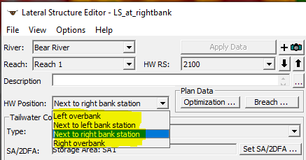
In Lateral Structure Editor window, HW Position must be selected: Left/Right overbank, or Next to left/right bank station (Figure 8).
For a 1D river reach in HEC-RAS, there is only one single WSE value at a cross section but these WSE values vary along river profile direction. Different HW position settings will determine how a lateral structure is to be “connected” or “correlated” to cross sections, which will in turn impact how headwater elevations (WSE of cross sections) along river profile are interpolated and applied to lateral structure weir equations. Apparently, if the cross sections have the same downstream reach lengths for LOB, Channel, and ROB, a HW position of left/right overbank or next to left/right bank station does not matter since no matter which position is selected, the “connection” between cross sections and a lateral structure is not to make a difference.
However, when the cross section downstream reach lengths for LOB, Channel, and ROB are different, the HW position setting needs to be carefully selected.
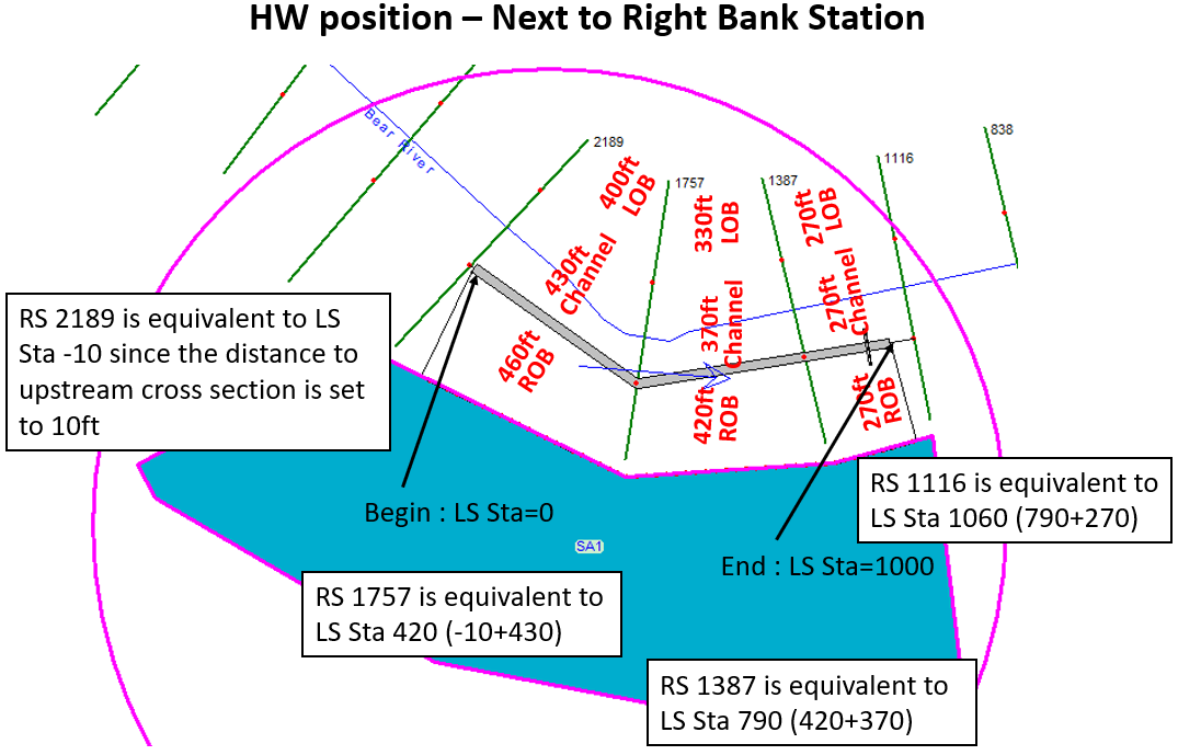
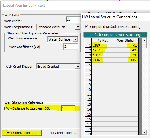
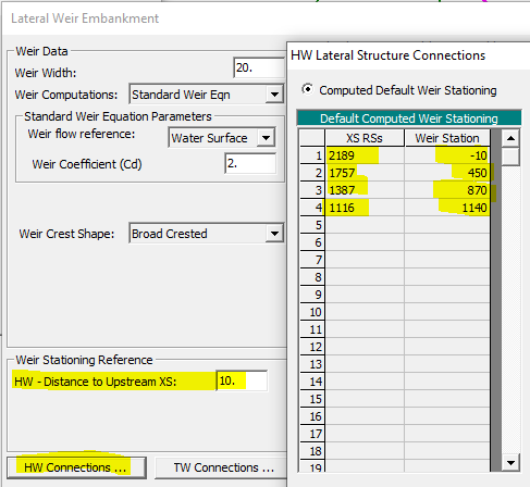
As shown in Figure 9, a 1000ft long lateral structure is established between cross section 2189 and 1116 and its HW position is set to Next to right bank station. The lateral structure (Begin, LS Sta=0) is 10ft away from its upstream cross section 2189. The “connection” between cross section 2189/1757/1387/1116 and the lateral structure is explained and shown in Figure 9 and Figure 10.
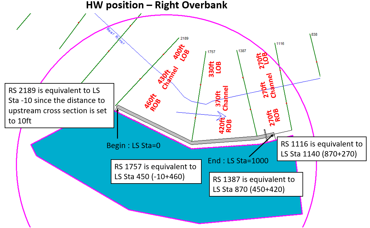
Now change the lateral structure HW position to Right overbank and due to the downstream reach lengths of ROB are different from those of the channel, the “connection” between the cross sections and the lateral structure is different from the above (Figure 11 and Figure 12).
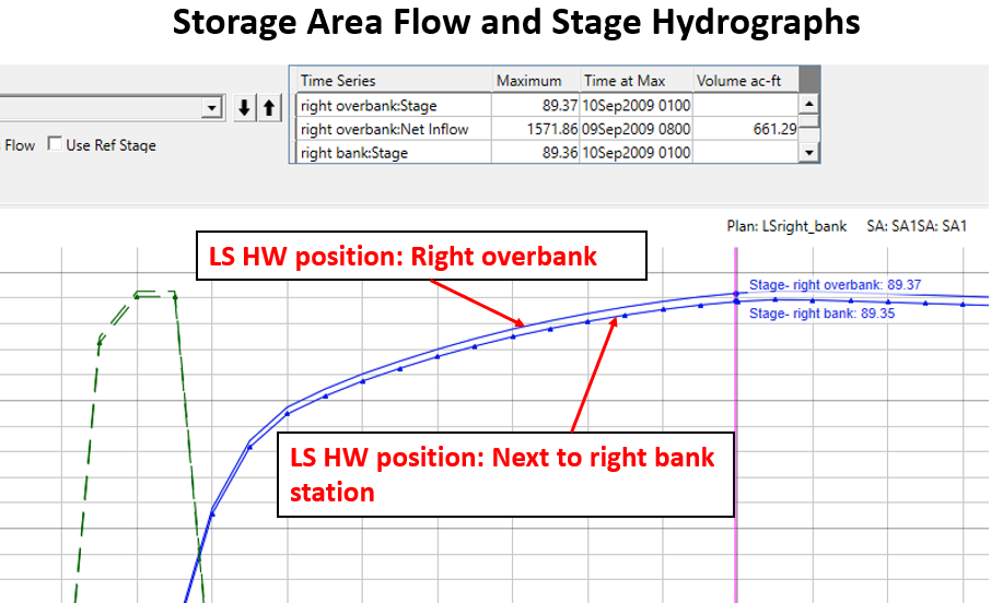
In the examples above, the “connection” between the cross sections and the lateral structure is different with different HW positions, which in turn impacts the headwater interpolation along the lateral structure, and therefore the modeling results are different (Figure 13).
Other topics about lateral structures can be found in this post.
Leave a Reply