HEC-RAS Lateral Structure (2 of 2)
A lateral structure (LS) in HEC-RAS, parallel to the centerline of a river, is often used to connect a river reach to a 2D flow area, a storage area, or another river reach to divert flows from a river to its overbank areas or another river. The basics of lateral structures can be found in this post, including LS setup, geo-reference LS, weir/embankment elevation, and HW position. This post is to focus on the rest of the details about lateral structures.
1. Flow Directions
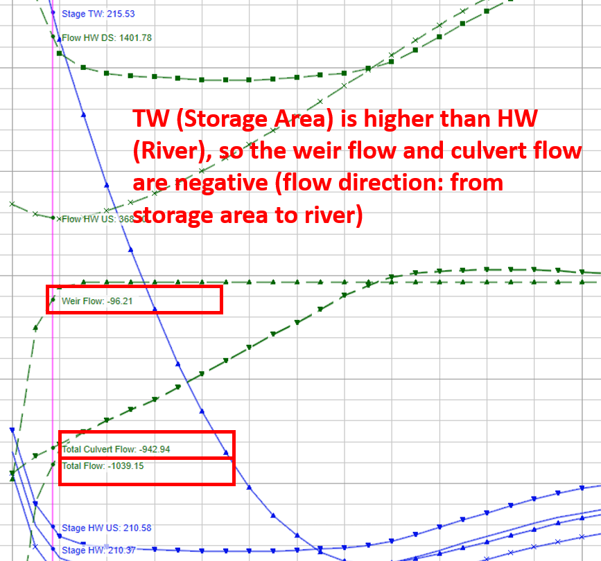
For a lateral structure, the river (HW) is its upstream side and the TW side is its downstream side. Depending on HW or TW elevations, the flow direction over a lateral structure can be reversed, however, because of the definition of HW and TW, the weir flow values will be negative when TW is higher than HW (Figure 1).
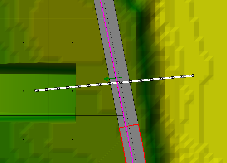
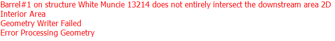
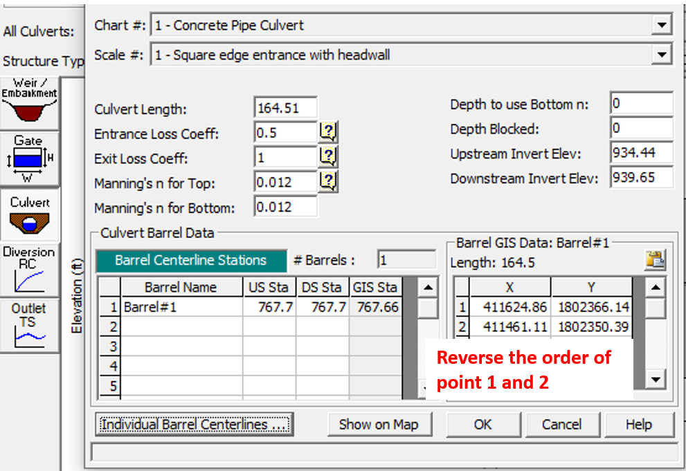
If a culvert is included in a lateral structure, its upstream and downstream sides are defined the same way as the lateral structure. When inserting a culvert in a lateral structure, its centerline GIS point should be drawn starting from the river side and a flow direction arrow will indicates the correct setup as shown in Figure 1A. If the centerline GIS coordinates are in the reverse order, an error message “Barrel#1 on structure … does not entirely intersect the downstream area 2D…” will pop up when running the model (Figur 1B). To fix this error, simply reverse the order of the GIS points coordinates in Figure 1C.
Similarly, if a culvert pipe is used to drain the storage area (detention basin), its upstream invert (river side) usually should be lower than its downstream invert (storage area or basin side, Figure 2)
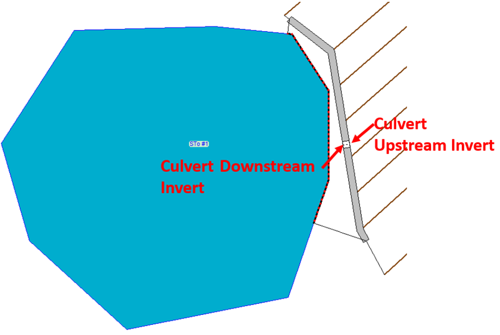
How to properly set up a culvert can be found in this post.
2. Weir Coefficients of Lateral Structures
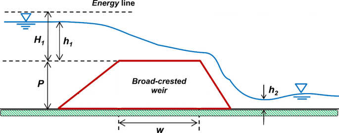
A normal weir flow (weir is perpendicular to the flow direction) is calculated using the Standard Weir Equation (Figure 3, HEC-RAS Hydraulic Reference Manual). In SI Units with Q in cubic meter per second and L & H in meter, C unit is m^0.5/sec, whose numerical value is C (ft^0.5/sec) x 0.3048^0.5.
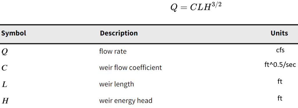
HEC-RAS Hydraulic Reference Manual defines H as Energy Head which includes the velocity head, however, other textbooks and manuals consider H as Potential Head (depth of flow above the weir crest). A more detailed discussion can be found at the end of this post.
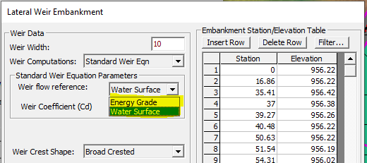
For a lateral structure by an 1D river, because the velocity in the lateral direction is zero, HEC-RAS Hydraulic Reference Manual recommends using the water surface of the flow (depth of flow above the weir crest) to calculate lateral structure weir flows in Standard Weir Equation, however, a modeler does have the option of choosing the energy head (Energy Grade) (Figure 4).
Because of additional head and momentum losses when water is diverted to a lateral structure/weir from its downstream direction, usually the weir coefficient of a lateral structure is lower than those of inline weirs (Table 1). A weir coefficient can be as low as 0.2 to 0.5 if the lateral structure is only an overland flow interface between the 1D river and the 2D flow area or storage area.
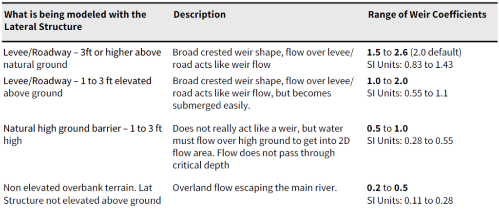
The above lateral structure weir coefficients are significantly lower than the inline structure weir coefficients, for example, HEC-RAS Hydraulic Reference Manual suggests using a weir coefficient of 2.6 for flow over a typical bridge deck and a weir coefficient of 3.0 for flow over elevated roadway approach embankments
The lateral structure weir coefficient may also be calculated by Hager’s Equation which has not gained its popularity in the engineering community so far.
The lateral structure weir crest shape determines how the weir coefficient will be reduced due to the submergence at downstream side. A broad crest shape weir is probably applicable to most of the applications unless there is a need to use other shapes. When there really is no weir and the flow just travels overland, the “Zero Height” weir crest shape should be selected.
3. Overflow Computation Methods
There are two ways to calculate the flow over a lateral structure: Normal 2D Equation Domain or Use Weir Equation (Figure 5). Generally, if the overflow acts like a typical weir flow (Figure 6), probably using weir equation is a better choice; and on the other hand, if the lateral structure is not elevated (thus overland flow over it) or the weir flow is highly submerged, choose Normal 2D Equation Domain. For a new project, it is a good idea to test both methods to see which one produces a more reasonable result without causing the model to go unstable.

4. Model Stability with Lateral Structures
Inline and Lateral Structures tend to cause a HEC-RAS model to become unstable, and this is particularly true when a lateral structure is present. To stabilize an unstable HEC-RAS model due to lateral structures, a modeler can try several different methods:
- Reduce time steps (sometimes increasing time steps may help)
- Use several shorter lateral structures instead of a single long lateral structure
- Position lateral structures on high grounds, revise 2D flow area or storage area boundaries extend, trim river cross sections, refine 2D flow areas using smaller cells
- Test Normal 2D Equation Domain or Use Weir Equation; if use weir equation, try to use a smaller weir coefficient
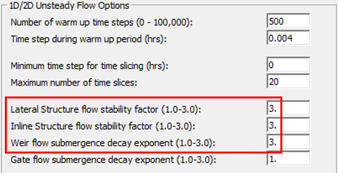
- Set Lateral Structure flow stability factor and/or weir flow submergence decay exponent to 2.0 or 3.0 instead of the default value of 1.0 (Figure 7).
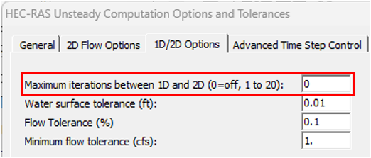
- Turn on maximum iterations between 1D and 2D by entering a non-zero value (3 or 4 to start with) in Figure 8.
- Adjust initial and/or other boundary conditions if necessary
- Use appropriate 1D/2D warm up time and steps, 2D initial conditions time & ramp up fraction (for more details, refer to this post)
- Apply different 1D and 2D solver engines.
5. Junction Modeling by a Storage Area and Lateral Structures
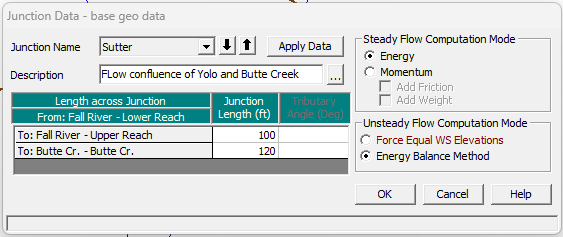
Traditionally when two rivers meet (split or converge), a junction is created in HEC-RAS (Figure 9). The lengths across the junction and the computation methods for steady and unsteady flows need to be defined (Figure 10).
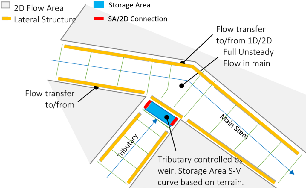
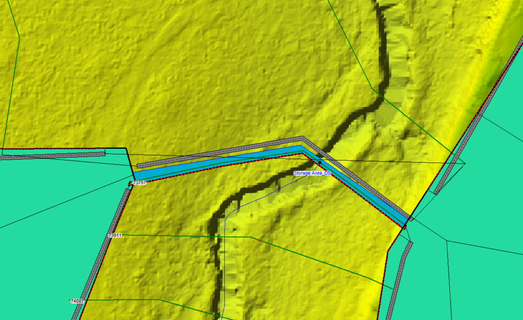
A lateral structure along a main stem and a storage area can work together to represent a junction as shown in Figure 11 and Figure 12, according to Harris County Flood Control District (HCFCD) HEC-RAS 1D Modeling Guidelines. This “special ” junction setup produces a more stable solution comparing to the traditional junction setup under certain unsteady flow conditions. The main stem lateral structure (just downstream of the storage area) weir coefficient can be taken as 2.0 but a smaller or larger value sometime may give a more reasonable result for certain field conditions. The rest of lateral structures or SA/2D Connection weir coefficients can be anywhere between 0.2 to 2.6 (0.5 to 1.0 are probably more common) or using Normal 2D Equation Domain to compute the overflow as indicated above. The storage area elevation-storage curve can come from the automatic calculation in HEC-RAS “Compute E-V table from Terrain”, or for simplicity, just use the “Area times depth method” by assigning a surface area in acres and a min elevation.
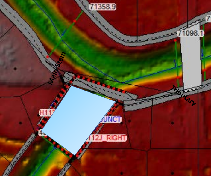
The storage area is connected directly to the most downstream cross section of the tributary by moving the tributary centerline end point inside the storage area boundary. The storage area actually works as the downstream boundary condition of the tributary and its initial condition (WSE) can be established by the modeler on an as-needed basis.
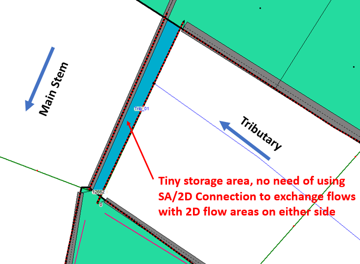
To further simplify the configuration of the “special” junction, a tiny storage area (say, 5ft or 10ft long along the tributary flow direction) along the tributary flow direction can be modeled to eliminate the need of SA/2D connection with 2D flow areas (Figure 13 and Figure 14).
Discussion: Energy Head or Potential Head (Depth of Flow) for H in Standard Weir Equation?
As stated above, HEC-RAS Hydraulic Reference Manual defines H as Energy Head in the Standard Weir Equation, however, other textbooks and manuals consider H as Potential Head (depth of flow above the weir crest).
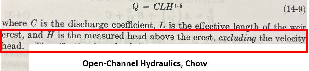
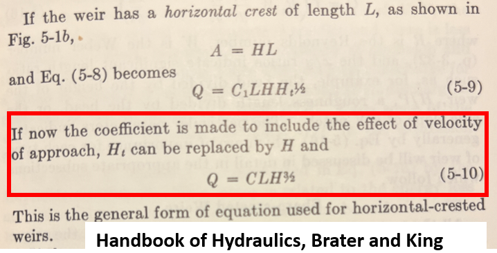
Chow (Figure 15) and Brater & King (Figure 16) suggested H should be the measured head (water surface) above the crest, excluding the velocity head since the effect of approach velocity has been included in the weir coefficient C (or discharge coefficient as named by Chow).
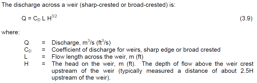
FHWA HDS 4 Introduction to Highway Hydraulics also defines H as the depth of flow above the weir crest which typically is measured at a distance of about 2.5H upstream of the weir (Figure 17).
Fortunately, the velocity head is probably insignificant comparing to the potential head so the final result will not vary much no matter which H is applied in a Standard Weir Equation. Choosing an appropriate C value overweighs the types of H to be used for most applications.
Leave a Reply