Modified Puls Storage Routing By Detention Basin Analysis Of Hydraulic Toolbox
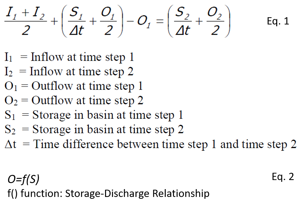
The modified puls storage routing technique is widely used to size a detention basin by routing inflow hydrographs (Figure 1). The two unknowns, O2 and S2 , can be solved by coupling Eq. 1 and Eq. 2.
The modified puls routing was performed by hand calculation or in a spreadsheet in the past; today, it can be easily done in H&H programs including HydroCAD and SWMM. This post introduces another H&H tool to solve the modified puls routing: the detention basin analysis function of Hydraulic Toolbox, which is a free program developed by FHWA.

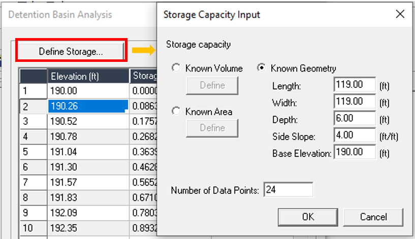
The detention basin from these two HydroCAD posts (1 and 2) is to be converted to an Hydraulic Toolbox detention basin analysis project. First, the detention basin storage is defined by its geometry in the same way as done in HydroCAD (Figure 3).
Second, the outflow structures need to be configured: orifices can be added by “Add Riser” (Figure 4) and the top opening of a riser for overflow purpose is entered as a standpipe (Figure 5). A rectangular shape top opening can not be defined in standpipes so in this example, it is approximated by a circular opening with a diameter of 4.5ft (same area as 4ft x 4ft rectangular opening).


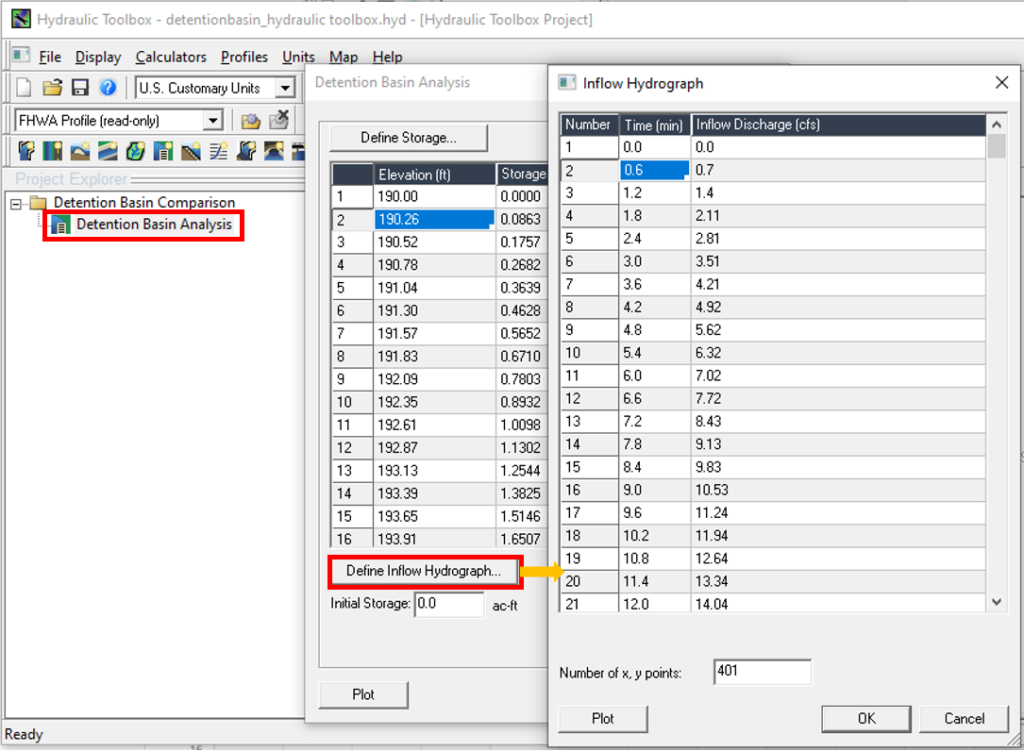
Last, the 100-yr inflow hydrograph from HydroCAD output tables is copied into Hydraulic Toolbox (Figure 6). The time in HydroCAD is in the unit of hour and it needs to be converted to minute before being copied to Hydraulic Toolbox.
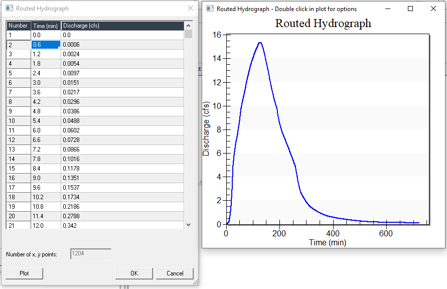
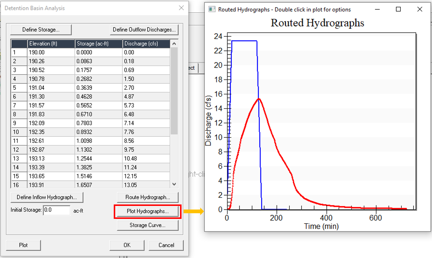
The detention basin modified puls routing can now be solved. Click “Route Hydrograph…” to find out the 100-yr outflow hydrograph and the time series table (Figure 7), or click “Plot Hydrographs…” to compare the 100-yr inflow and outflow hydrographs (Figure 8).
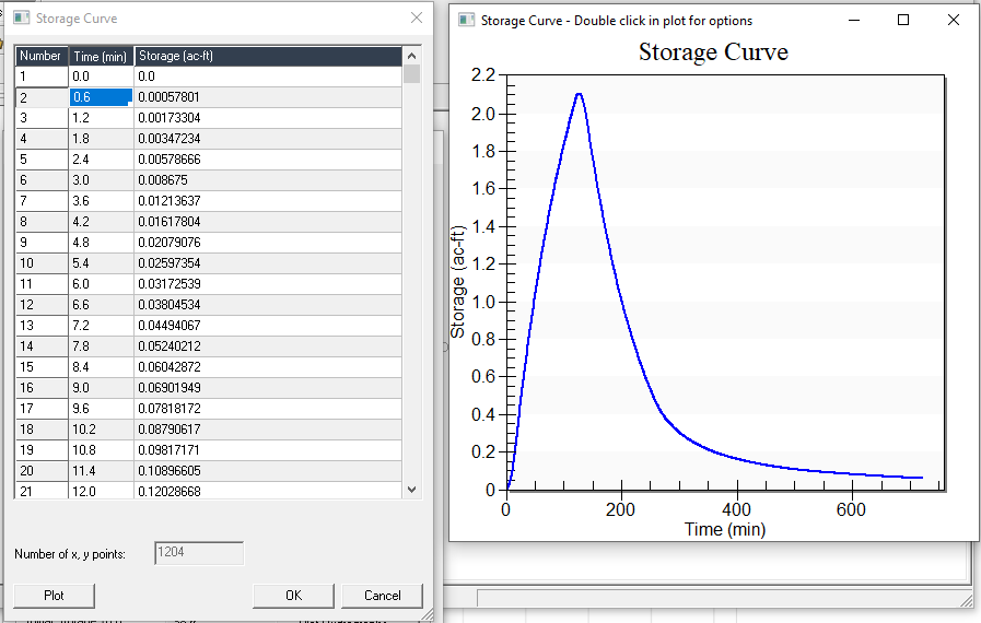
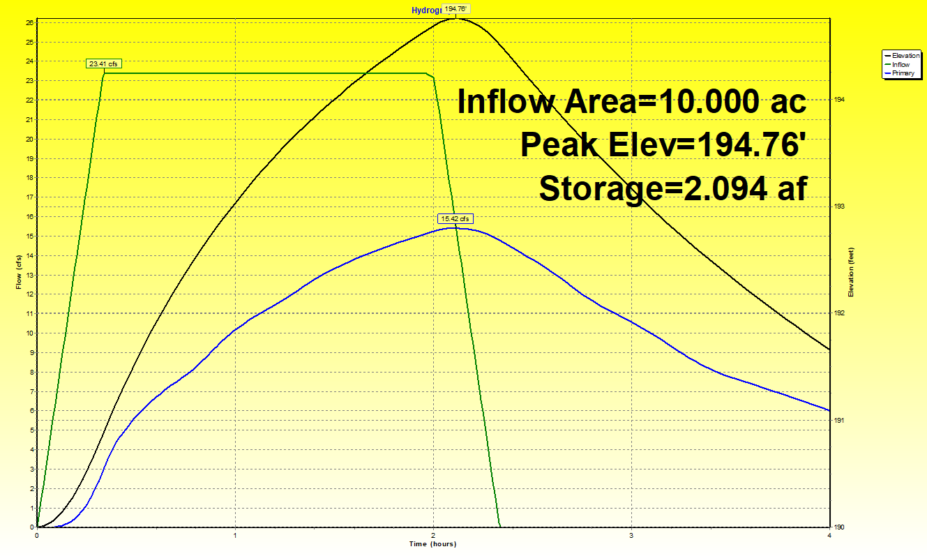
The detention basin storage can be reviewed by clicking “Storage Curve…” (Figure 9). In the example, the maximum 100-yr detention storage is 2.105 ac-ft, very close to the result of HydroCAD, 2.094 ac-ft (Figure 10).
The detention basin elevation vs discharge & storage curves can be plotted by clicking the “Plot” button as shown in Figure 11. From the plot, the overall performance of the detention basin with a given design can be evaluated and the rest of the two results can be found out if any one of the three variables (elevation, discharge, or storage) is known.
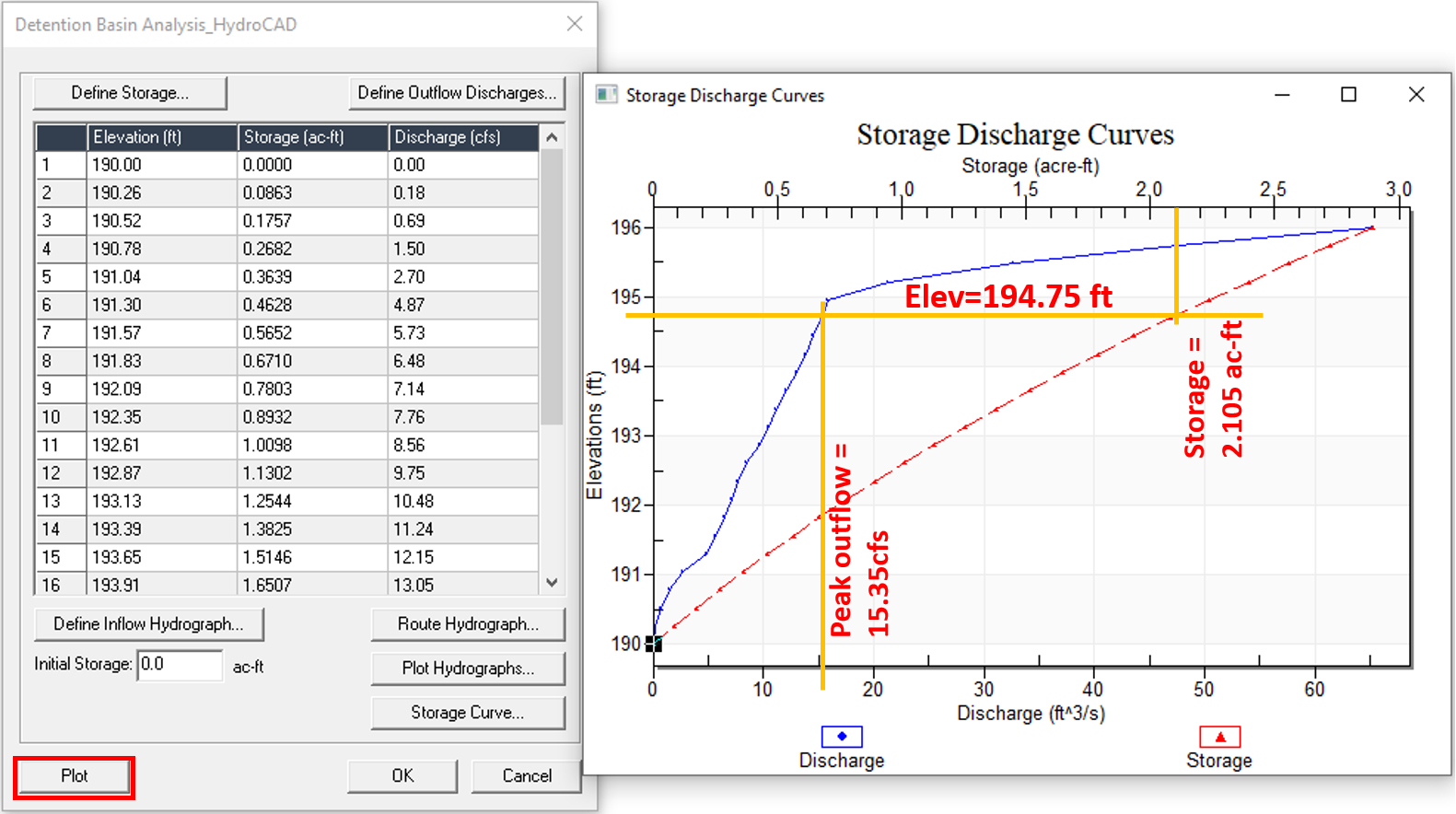
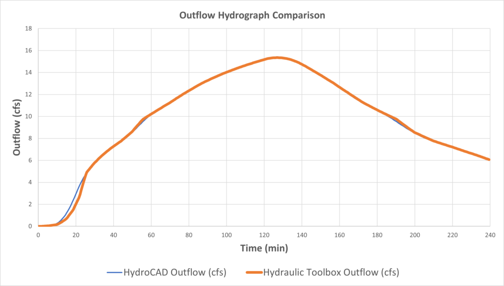
The outflow hydrograph of the Detention Basin Analysis of Hydraulic Toolbox was compared with that of HydroCAD and they match each other well (Figure 12). The difference at the beginning of the routing is because Hydraulic Toolbox and HydroCAD handle the low flow condition differently (an orifice operates like a weir under small headwater). For the example detention project, the 100-yr peak outflow rate of Hydraulic Toolbox Detention Analysis is 15.35cfs, while the 100-yr peak outflow of HydroCAD is 15.42cfs. The difference between the two H&H program results is insignificant.
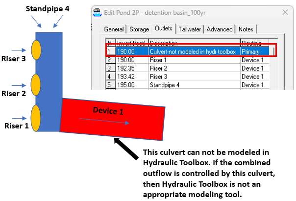
It shall be noted that the outflow culvert pipe (the culvert, Device 1 in HydrocAD) can not be modeled in Hydraulic Toolbox as illustrated in Figure 13. Normally, this culvert is designed to be large enough to not work as a flow-controlling structure, and therefore it is acceptable not to model it.
Overall, the detention basin analysis function of Hydraulic Toolbox is a very easy to use tool for some simple detention basin design tasks which require modified puls storage routing. Unlike in HydroCAD, users have to calculate inflow hydrographs externally as input for Hydraulic Toolbox. Users have no control on tailwater setting in Hydraulic Toolbox, and by default the program assumes a free outfall condition. Apparently, the unique HydroCAD “nesting” outflow structure feature (an outflow structure is discharging into another one) can not be implemented in Hydraulic Toolbox.
Leave a Reply