Modeling Skewed Bridge in HEC-RAS
The hydraulic opening width (area) of a skewed bridge is less than its unskewed value, which in turn would adversely impact the bridge hydraulic performance. The skew angle is defined as the angle between the actual river flow direction under bridge and the bridge orientation. HEC-RAS manual states that when a bridge is highly skewed, most likely the flow will turn somewhat before it goes through the bridge opening so the skew angle should not be calculated based on the direction of the flow upstream of the bridge.
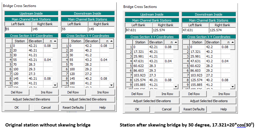
For a skewed bridge (Figure 1), cross section 2 and 3 in HEC-RAS lingo (bounding cross sections of a bridge) should be cut parallel to bridge faces and these two cross sections will be skewed together with the skewed bridge later. Stations of cross section 2 and 3 will be measured along their actual orientation (Figure 2) and station correction will be made automatically by HEC-RAS when specifying the bridge skew angle.
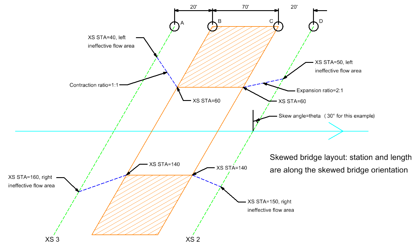
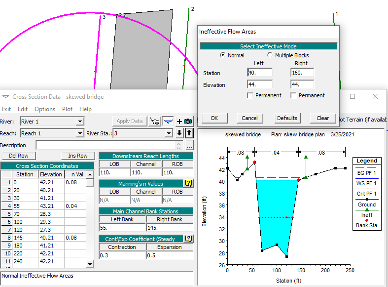
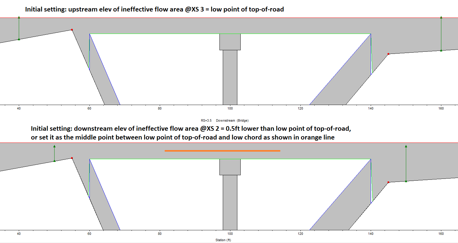
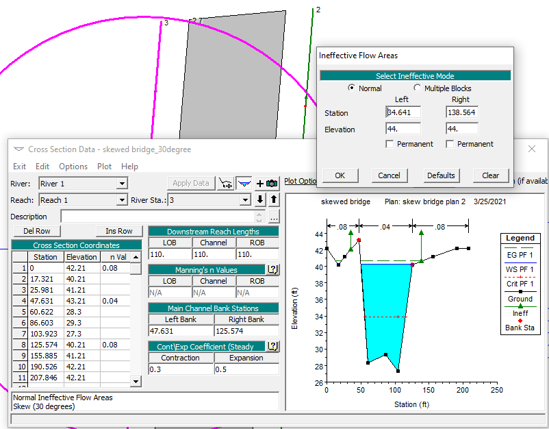
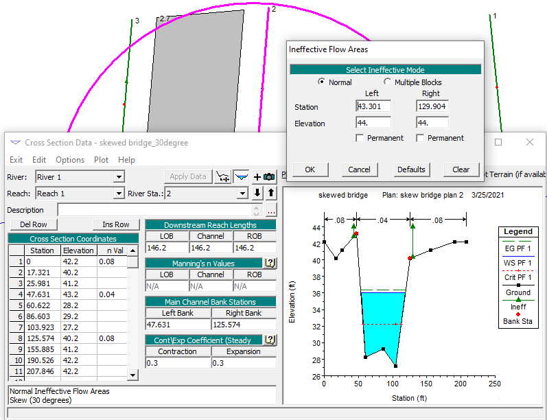
Ineffective flow areas should be established at Cross Section 3 and 2 as shown in Figure 1 using contraction ration of 1:1 an expansion ration of 2:1 for low flows or pressure flows to pass through the bridge opening. When a weir flow passing the bridge opening (overtopping bridge deck), these ineffective flow areas should be turned off – for this reason, the elevation of ineffective flow areas at Cross Section 3 (upstream) should be set up initially as the low point of top-of-road; and for Cross Section 2 (downstream), its ineffective flow area elevation should be initially set up as 0.5ft lower than the low point of top-of-road or somewhere in between the low point of top-of-road and the low chord as shown in Figure 3. After the initial setup, the downstream ineffective area elevation can be adjusted by trial and error method so that it is lower than any weir flow (overtopping) WSE profiles but higher than all other WSE profiles of pressure and low flows.
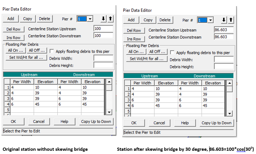
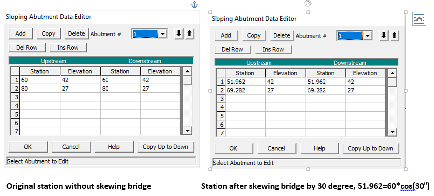
Bridge deck, pier and abutment stations should also be measured and entered along the actual bridge orientation (Figure 4) and like cross section 2 and 3, station correction will be made automatically by HEC-RAS when specifying the bridge skew angle.
After editing/entering station/elevation/other data for bridge and cross section 2 and 3, go to bridge data editor window and click Options—> Skew Bridge/Culvert … to enter a skew angle (Figure 5) to skew bridge and cross section 3 and 2 by checking on Skew Upstream/Downstream XS the same amount as the deck. Leave the Pier Skew Angle to zero (0) for now.
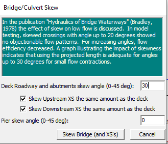
Stations of cross section 3 and 2 (including their ineffective flow area definition), bridge deck, pier, abutment, and bridge internal cross section are all to be updated automatically by a factor of COS(theta) after clicking Skew Bridge (and XS’s) in Figure 5. The skew angle can be changed back to zero (0) and the updated stations will be restored to their original unskewed values. Comparison for bridge deck, pier, abutment, internal cross sections, and Cross Section 3are shown in Figure 6 to 10.
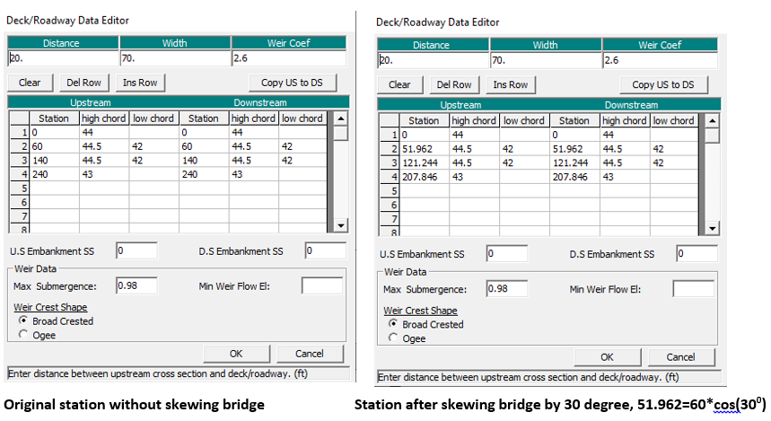
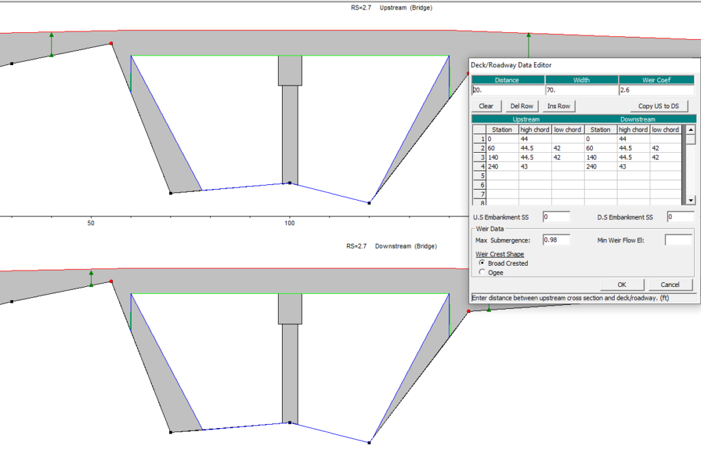
In Bridge Deck/Roadway Data Editor (Figure 6), the distance (20) and width (70) are not changed after skewing the bridge, and this is because these two values are measured along the stream (flow direction) per HEC-RAS user’s manual (distance of AB and BC in Figure 1) and they are not impacted by bridge skew angles.
The ineffective flow area station definition of Cross Section 2 and 3 may need to be adjusted manually since the distance (20) does not change after skewing the bridge. In Figure 10, the new ineffective flow area of Cross Section 3 is at station 34.614 (=40*cos(30)) and 138.564 (=160*cos(30)) and the new bridge opening station is station 51.962 and 121.244 in Figure 6. If using 20ft as upstream distance from Cross Section 3 to bridge face, the new ineffective flow area station should be adjusted to 51.962-20=31.962 and 121.244+20=141.244 respectively instead of 34.614 and 138.564. Similarly, the Cross Section 2 ineffective flow area station definition should be adjusted to 51.962-20/2=41.962 and 121.244+20/2=131.244 instead of 43.301 (=50*cos(30)) and 129.904 (=150*cos(30)) shown in Figure 11.
When interpolating a cross section in between two skewed cross sections in HEC-RAS, the interpolated cross section is normal to the river flow direction and thus its stations are measured along and in reference to the normal cross section cut line. For this reason, for a skewed bridge in between two interpolated cross sections, when starting to skew the bridge, the option of skewing upstream/downstream cross section shall be unchecked and disabled.
In a skewed bridge, piers can be either skewed or unskewed (Figure 12). Since HEC-RAS can only handle a continuous pier/bent, a skewed pier will have a very big opening blockage width which depends on skew angle, bridge deck width and pier width. For skewed pier, its skew angle can be different from or the same as bridge skew angle and its value can be entered by going to bridge data editor window and click Options—> Skew Bridge/Culvert … (Figure 5)
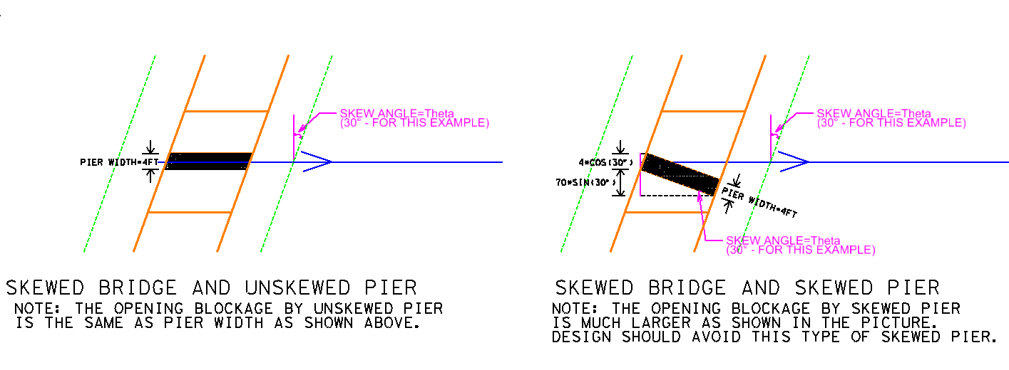
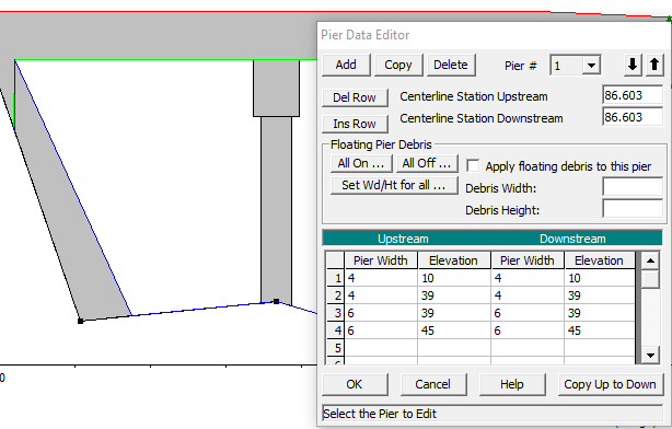
In Figure 12, assume the pier width=4ft, bridge deck width=70ft, and pier skew angle is the same as bridge skew angle=30degree, then the skewed pier equivalent width (blockage) is 4*cos(30)+70*sin(30)=38.46ft as shown in Figure 14.
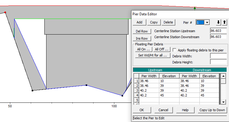
As shown in Figure 14, a skewed bridge pier will reduce bridge opening greatly and its application should be avoided if possible when designing a bridge.
Leave a Reply