Modified Rational Method Application in HydroCAD and XPSWMM
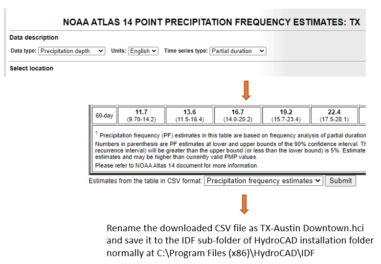
HydroCAD and XPSWMM have the modified rational method built into the programs and it is very convenient to apply the method in either of the modeling tools. One or more IDF curves are needed to supply the intensity value I. The IDF should be provided by local regulating agencies or downloaded from NOAA Atlas 14 Data Server. Follow the steps in Figure 1 (Austin, TX downtown area as an example) to download and save IDF to HydroCAD installation folder.
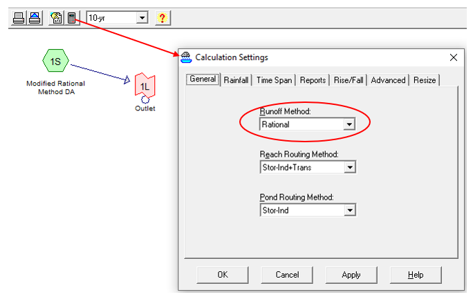
To demonstrate the modified rational method application in HydroCAD, a very simple model was established with only one drainage area and one outlet. Under Calculation Settings, General Tab, the Runoff Method needs to be set as “Rational” to apply the modified rational method (Figure 2).
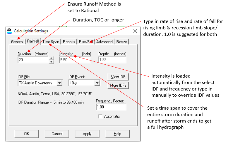
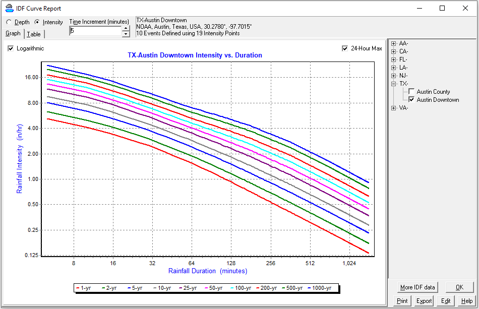
Under Rainfall Tab of Calculation Settings, the modeler needs to choose appropriate Duration, IDF file and frequency event or manually type in the intensity value as shown in Figure 3. The modeler should also visit Time Span and Rise/Fall Tab to set them up correctly. The selected IDF curves are shown in Figure 4 which were downloaded early.
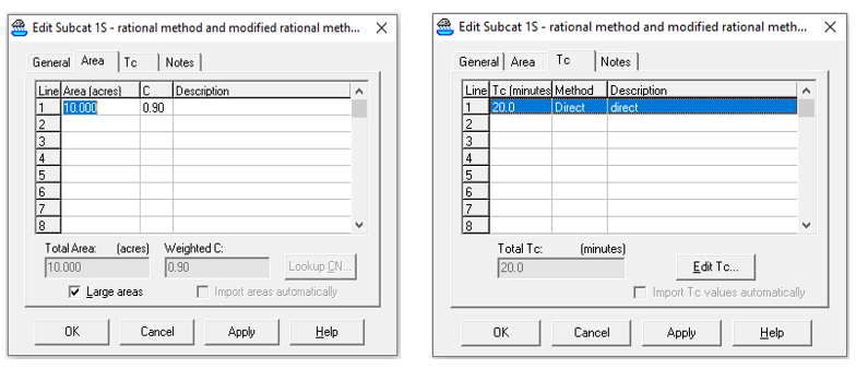
The sample drainage area “1S” is 10 acres. Drainage Area “1S” TOC is 20 minutes and its runoff coefficient C is 0.90 (Figure 5). Figure 6 shows its modified rational method hydrograph created by HydroCAD when the storm duration is entered as 40 minutes.
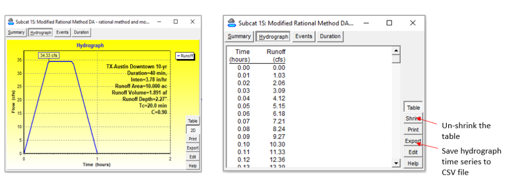
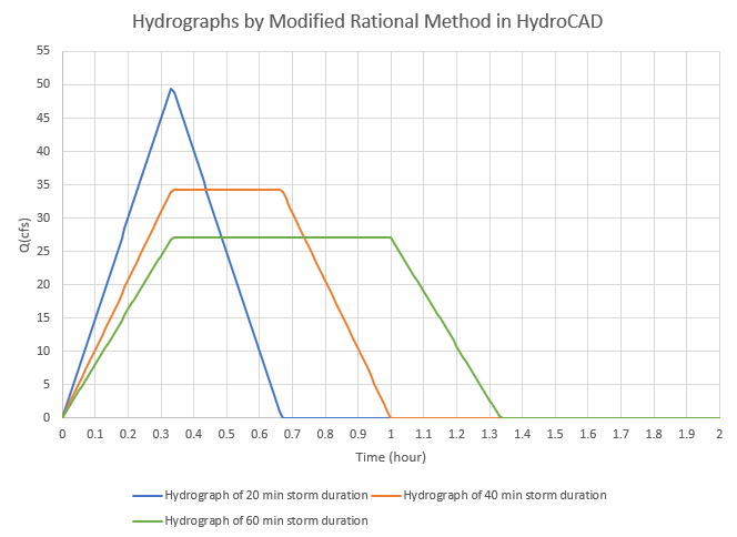
Several different storm durations are tested and their hydrograph time series data is exported to CSV/Excel files for comparison purpose (Figure 7).
Note that in HydroCAD rational method, the rainfall intensity calculation is based on the rainfall duration in Figure 3, not the subcatchment drainage area Tc in Figure 5 as explained in this post. The Tc value will only impact the shape of the modified rational method hydrograph in terms of rising and recession limbs.
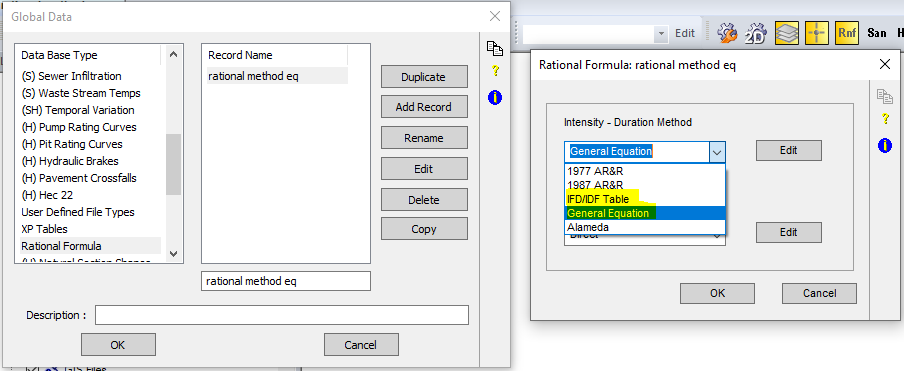
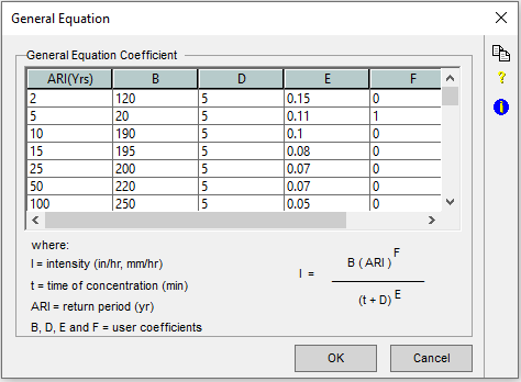
To use rational method in XPSWMM, a Rational Formula must first be created under Global Data (Figure 8). Click “Edit” button on Figure 8 to choose the method to define Intensity-Duration-Frequency relationship which can take the format of IDF Table or General Equation (Figure 9).
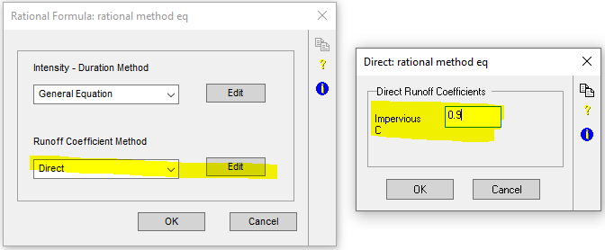
The impervious area runoff coefficient C is defined by selecting Runoff Coefficient Method as “Direct” and enter its value by clicking “Edit” button on the right side of “Direct” (Figure 10).
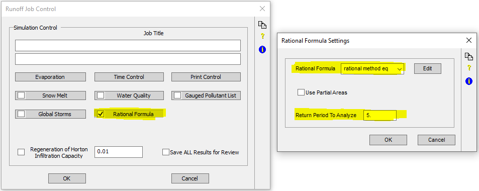
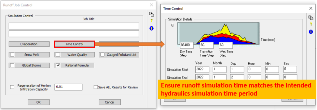
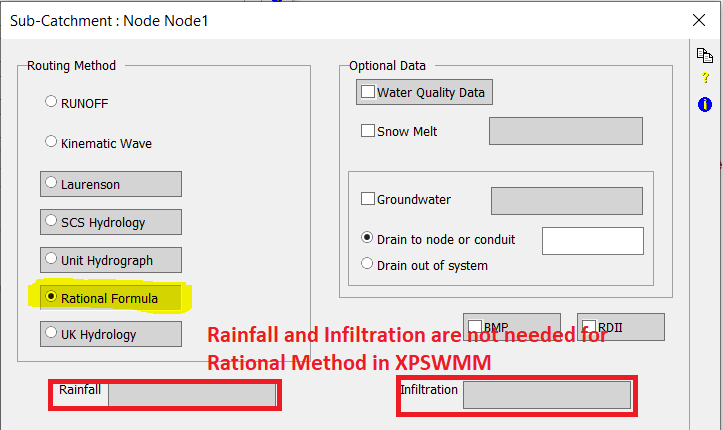
Now, switch XPSWMM to “Runoff” mode and open Runoff Job Control window to click and enable “Rational Formula“. Under “Rational Formula“, select the rational formula defined previously in Global Data and enter the return period (frequency) to be analyzed (Figure 11). Open Time Control to ensure runoff simulation time matches the intended hydraulics simulation time period (Figure 12).
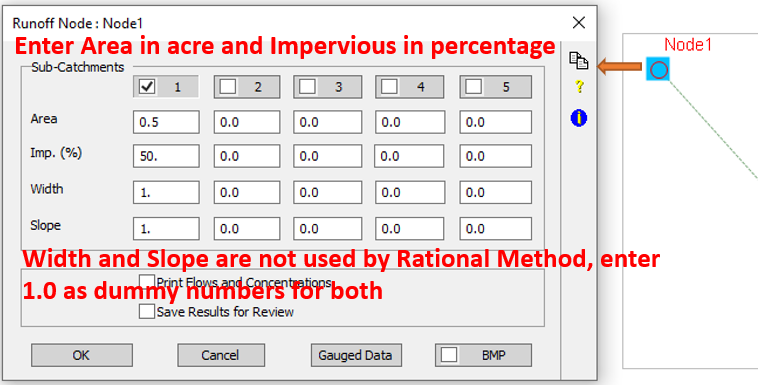
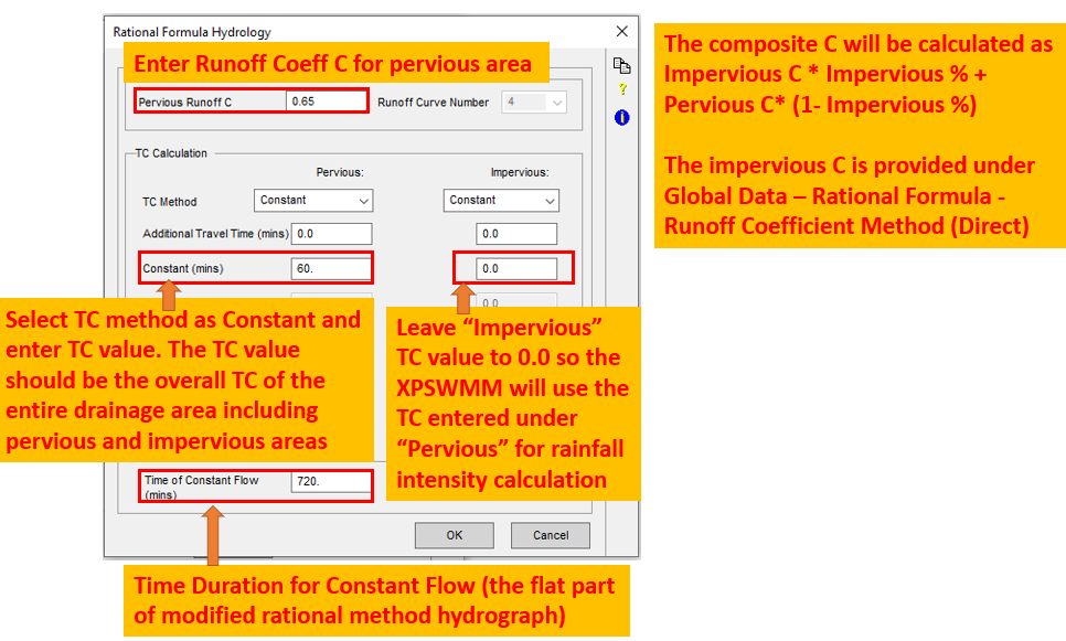
Now, edit the nodes runoff data to supply drainage area in acre and impervious area in percentage (Figure 13). Select and click Rational Formula in Figure 14 to type in Runoff Coefficient C for pervious area, time of concentration Tc(min), and constant flow duration time (min) in Figure 15. Tc values can be entered for “Pervious” and “Impervious” respectively and it appears XPSWMM will use the larger one for the entire drainage area (pervious and impervious combined) to calculate rainfall intensity. To avoid any confusion, it is recommended to only enter the Tc of the entire drainage area under “Pervious” while leave Tc of “Impervious” as 0.0.
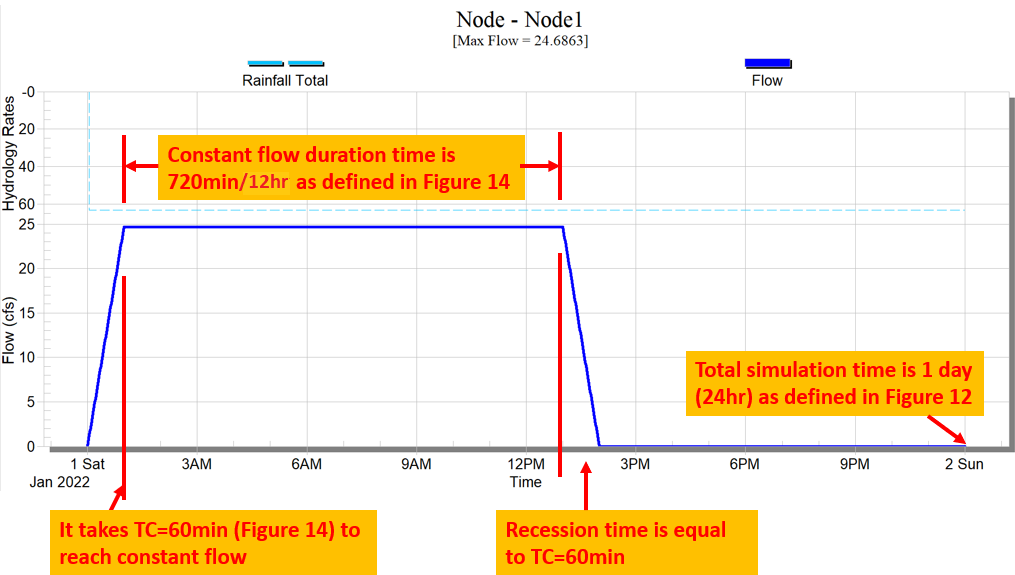
The resulted rational formula hydrograph is shown in Figure 16 for the example Node1. The max flow (peak flow) is 24.6863 cfs, which can be verified easily by hand calculation.
HydroCAD and XPSWMM handle the rational method differently:
1. HydroCAD rational method rainfall intensity calculation is based on rainfall duration, while XPSWMM rational method rainfall intensity is calculated by Tc regardless of time of constant flow values;
2. HydroCAD allows users to enter rainfall duration in the overall program setting and this duration (and thus rainfall intensity) will be applied to different subcatchments in the model regardless of their time of concentration; XPSWMM does not have the option to enter a rainfall duration for the entire model, even though at the individual node/subcatchment level, time of constant flow can be entered and it may be translated to rainfall duration (= Tc + time of constant flow);
3. For reason #2, the outflows of different subcatchments in HydroCAD from rational method can be routed and combined together since they are generated under a single rainfall event (the same duration and intensity based on that duration); while in XPSWMM, theoretically it is hard to justify routing/combining the outflows from different nodes/subcatchments when they have different time of concentration (rainfall intensities) and durations.
Last, it should be noted that rational formula hydrographs should NOT be combined, routed or used together with other types of hydrographs since there is no correlation between them.
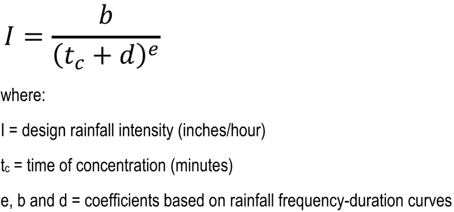
How to define an IDF file in HydroCAD using e, b, d coefficients:
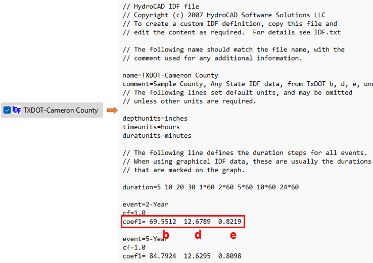
Rainfall intensity can be defined by using e, b, d coefficients as shown in Figure 17.
In HydroCAD, the IDF files (*.hci) are found at the HydroCAD installation folder: Program Files (x86)/HydroCAD/IDF. To create a new IDF file, under the same folder above, simply make a copy of an existing *.hci file and rename/revise it as needed (Figure 19). For more detailed instruction, refer to the IDF.txt file under the IDF folder which comes with the HydroCAD installation.
1 COMMENT