SWMM Nonlinear Reservoir Runoff Method and Its Application in XPSWMM and InfoWorks ICM
Unit hydrograph transform method for precipitation-runoff process is widely used by many H&H modeling tools, but EPA SWMM has its own method known as nonlinear reservoir runoff method which treats a subcatchment as a shallow reservoir and its runoff flow is a nonlinear function of the water depth of the reservoir by solving continuity equations (Figure 1). Since its introduction decades ago, SWMM nonlinear reservoir runoff method has been adopted by other H&H modeling tools such as XPSWMM and InfoWorks ICM.

Nonlinear reservoir runoff method can be mathematically described by continuity and Manning’s equations in Figure 2, where d, q, and then Q=q x A can be solved at each time step with given i, e, and f. Parameters required to carry out nonlinear reservoir runoff method include drainage area A, overland flow Manning’s n, depression storage ds, width W, and subcatchment slope S which should be measured along the overland flow path.
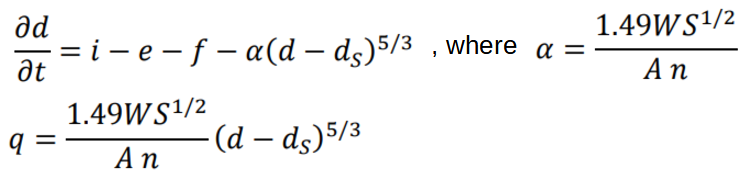
As can been seen from the equations, nonlinear reservoir runoff method eliminates the need of calculating Time of Concentration (TOC), which is often subjective and sometimes arbitrary, but it comes with its own price of estimating subcatchment characteristic width W.
EPA SWMM User’s Manual suggests that W be estimated as the quotient of the drainage area divided by the average maximum overland flow length. The maximum overland flow length is the length of the flow path from the remotest point to where the flow becomes channelized and it probably should be less than 100-500ft (common) or 1000ft (uncommon). Maximum lengths of several different possible flow paths should be investigated and averaged to calculate a characteristic width W. In an idealized rectangular shaped subcatchment, the width W can be estimated for two scenarios as illustrated in Figure 3A, but for almost all the real world subcatchments, calculating their width W is tricky to say the least.

For an irregular shaped subcatchment, the width W can be estimated by using a skew factor as explained in Figure 3B.

Nonlinear reservoir runoff method assumes that overland flow becomes runoff at outfall instantly when reaching a channel. This assumption is only valid if a drainage area is small and its channel flow path is short. For this reason, if a subcatchment is too large or its shape is too irregular, it probably needs to be further delineated to smaller sizes before applying the nonlinear reservoir runoff method. City of Winnipeg Wastewater Hydraulic Modeling Guidelines requires a subcatchment in InfoWorks to be less than 2 hectares (5 acres) when applying SWMM nonlinear reservoir method.
It is never a good idea to include too large a subcatchment in SWMM models in which channelized or pipe flows are dominant, but people tend to do it anyway. In this case, W absolutely needs to be calibrated.
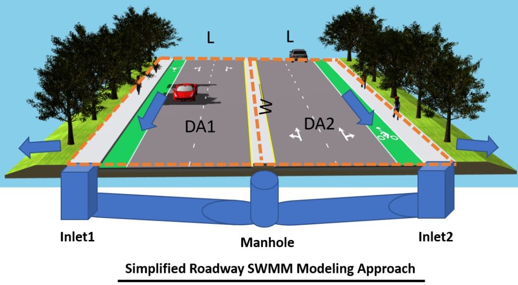
A simplified roadway SWMM modeling scheme is illustrated in Figure 3C. Depending on the required modeling level of details, two types of SWMM models can be set up:
- Inlet Level Modeling
Model each inlet explicitly: Each subcatchment (DA1 or DA2) width is W, Area is L x W, Slope is the pavement cross section slope (cross slope, usually 2%~3%) - Manhole Level Modeling
Model the manhole, not the individual inlets: The combined subcatchment (DA1 + DA2) width is 2W, Area is 2 x L x W, Slope is the pavement cross section slope (cross slope, usually 2%~3%). Most of the SWMM models can be established this way if the local hydraulic details at inlets are not needed.
The subcatchment runoff flow rate is more sensitive to width W than to overland flow path slope S (Figure 4) and it should be calibrated if possible.

In EPA SWMM, to better describe a subcatchment characteristics, 3 subareas can be defined: Impervious Area with Depression Storage, Impervious Area with Zero Depression Storage, and Pervious Area (Figure 5A), although they do not need to be present all together at the same time. The rest of subcatchment parameters in EPA SWMM include: area, width W, slope, Manning’s n for impervious area and pervious area, depression storage for impervious area and pervious area, infiltration, and subarea routing method.

In XPSWMM, the SWMM nonlinear reservoir hydrology routing is known as “RUNOFF” method as shown in Figure 5B. An infiltration method has to be defined and selected (Figure 5C). Other SWMM nonlinear reservoir routing required parameters such as Depression Storage and Manning’s n are defined in Figure 5D.


InfoWorks ICM has the capability to apply SWMM nonlinear reservoir runoff method to a subcatchment, however, its implementation is not as straightforward as EPA SWMM or XPSWMM. Before creating a subcatchment with SWMM nonlinear reservoir runoff method, it is beneficial to read through this post to have a general idea on how subcatchment hydrology works in InfoWorks.
In InfoWorks ICM, the 3 subareas of EPA SWMM need to be defined as three separate runoff surfaces in subcatchment grid window (Figure 6), but again, you don’t need to create all of them at the same time if not needed. The impervious areas can be modeled by a runoff surface using “Fixed” runoff volume type with the fixed runoff coefficient of 1.0. As shown in Figure 6, “Runoff routing value” is for Manning’s n of overland flow of SWMM nonlinear reservoir runoff method. “Runoff routing value” is NOT used for some other routing models widely used in the United States and its value can be simply set as 1.0 for these routing methods. “Routing model” needs to be selected as “SWMM” which means SWMM nonlinear reservoir runoff method.

City of Winnipeg Wastewater Hydraulic Modeling Guidelines requires each subcatchment to be assigned three separate runoff surface types using a similar area arrangement (Table 1) for SWMM nonlinear reservoir method.

Land use will need to be defined next. A land use basically is a combination of runoff surfaces with different percentages of areas. In Figure 7, two land use types are defined and Landuse_2 has more impervious area than Landuse_1 in terms of area percentages.

A sample subcatchment property editor is shown in Figure 8 which is set up to apply SWMM nonlinear reservoir runoff method. The width W in EPA SWMM is entered in the cell of “Dimension (ft)” and “Unit hydrograph definition” can be left as blank since UH does not play a role when a subcatchment uses SWMM nonlinear reservoir runoff method. Most of the cells not circled in Figure 8 are because they are not required for SWMM nonlinear reservoir runoff method and can be ignored. Finally and most importantly, each subcatchment needs to select a land use type defined previously (Figure 9). Example: DA1 uses Landuse_1 as its land use type. Because DA1 total area is 1.0 acre and Lanuse_1 has 60% defined as runoff surface 3 (pervious), therefore, DA1’s pervious area is 0.60 acre. Similarly, it is easy to figure out that DA1 impervious area with depression storage is 0.3 acre and impervious area with zero depression storage is 0.1 acre (Figure 10).


Some thoughts on SWMM nonlinear reservoir runoff method.
- Easy to build a model without the need of estimating TOC or selecting a UH transform method, however, not every regulating agency approves its use
- A subcatchment should NOT be too large in order to apply SWMM nonlinear reservoir runoff method. It is difficult to set up a certain upper limit, but it appears using several acres (say 5 acres or maybe even 10 acres) as maximum allowable subcatchment areas is reasonable.
- How to appropriately calculate subcatchment width W is critical and tricky. EPA SWMM User’s Manual and Hydrology Reference Manual are good sources for width W estimation.
- Width W can be estimated as the quotient of drainage area divided by average maximum overland flow length. The maximum overland flow length is the length of the flow path from the remotest point to where the flow becomes channelized and it probably should be less than 100-500ft (common) or 1000ft (uncommon).
- Width W can also be estimated using a skew factor as illustrated in Figure 3B for an irregular shaped subcatchment.
- Width W should be calibrated whenever it is possible
- Peak flows from Rational Method may be used to calibrate width W in case of lacking monitored flow rates. There isn’t a solid scientific reason to trust Rational Method more than other methods, but a lot of regulating agencies just love Rational Method due to its long application history.
Leave a Reply