Watershed Delineation Using HEC-HMS GIS Tools (Part 1 of 3)
The new HEC-HMS published around 2020 has some useful GIS tools to delineate a watershed using terrain data. Unlike HEC-GeoHMS, these standalone GIS commands are an integral part of HEC-HMS software which do not require ArcGIS environment. After a watershed is delineated, its area and other hydrologic parameters can be calculated directly within HEC-HMS. This post is to demonstrate new HEC-HMS watershed delineation and basin setup functions. A second post is to show HEC-HMS capability to merge/split subbasins (watersheds) and reaches (streams). Finally a third post is to demonstrate HEC-HMS hydrology parameter estimation capability.
This demonstration is for Bear Creek watershed, located at about 9 miles west of Johnsonburg, PA (Figure 1). DEM is downloaded from USGS (https://viewer.nationalmap.gov/basic/#/) and a step by step instruction of downloading USGS DEM can be found in this post. Previously, the watershed has been delineated using TauDEM Plugin in QGIS (refer to this post) and here we are going to use HEC-HMS V4.7 GIS tool to delineate it. The two delineated watersheds will be compared at the end of this post.
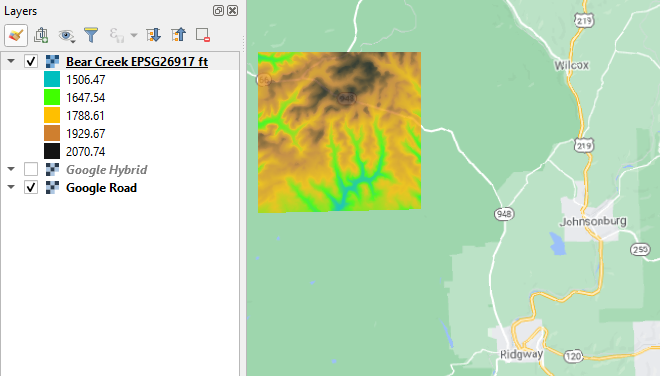
The files used for this demonstration can be downloaded here including the HEC-HMS project file, re-projected DEM file Bear Creek EPSG26917 ft.tif, and outlet shapefile outlet BC_final.shp.
The following is a step by step instruction of using HEC-HMS GIS tools to delineate watersheds and setup basins.
- Create a new HEC-HMS project file with the name of Bear_Creek_HMS47.
- Click top menu of Components, then Terrain Data Manager to add a new terrain data (DEM). In this example, a new terrain data named Bear Creek DEM is created by adding the re-projected DEM file of Bear Creek EPSG26917 ft.tif. The terrain data file used here should be in reference to a projected coordinate system (example: UTM zones, State Plane Coordinate System).
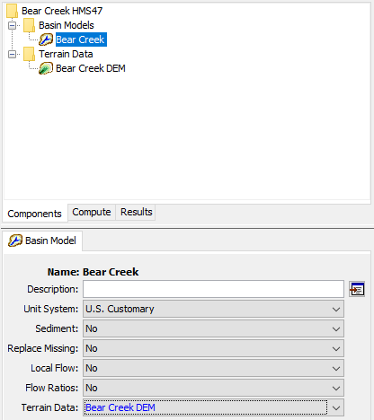
- Click top menu of Components, then Basin Model Manager to add a new basin model. In this example, a new basin model named Bear Creek is created through this step. Click the basin model of Bear Creek and in its editor window, select Bear Creek DEM as its Terrain Data (Figure 2). Because so far a GIS Coordinate System has not been defined in HEC-HMS, when you select Bear Creek DEM for Bear Creek basin model, a warning message will pop up asking you how to set up the coordinate system for the basin model (Figure 3), in this case, select “skip” so the coordinate system of Bear Creek DEM (actually it is from Bear Creek EPSG26917 ft.tif) will be used for the basin model.

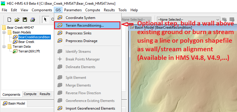
3A. Optional step – Terrain Reconditioning: starting from HEC-HMS V4.8, a tool for terrain reconditioning is added onto GIS menu (Figure 3A). This is an optional step and you can skip it and go to Step 4 – Preprocess Sinks directly if your terrain does not need to be reconditioned. For the detailed reconditioning instruction, refer to the HEC-HMS manual.
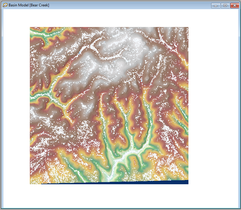
- Click top menu of GIS, then Preprocess Sinks to fill sinks of the terrain data to generate a hydraulically connected DEM which is superimposed on top of existing terrain data (Figure 4).
- Click top menu of GIS, then Preprocess Drainage to create two new files, Flow Direction and Flow Accumulation (Figure 5).
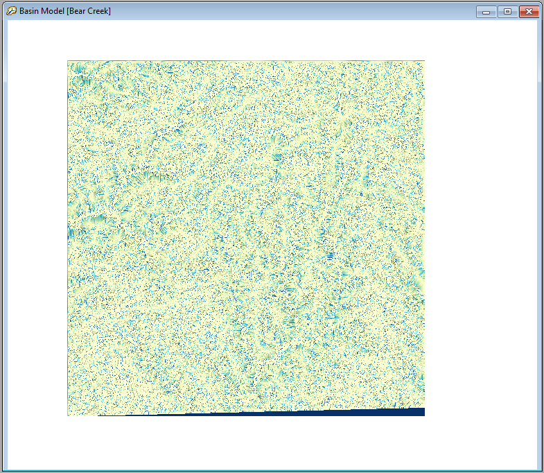
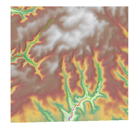
- Click top menu of GIS, then Identify Streams to create stream networks. A window will pop up asking you to specify a threshold for stream delineation, which is the minimum drainage area for HEC-HMS to identify a stream. A smaller value will create more subbasins and streams (reaches). For a new project, an appropriate threshold value may be determined by trial & error. For this tutorial, enter 2 square miles as the threshold value. This step creates a new Identified Streams file (Figure 6). On Figure 6, the green color on stream network means upstream end of a stream and red/purple color means downstream end of a stream.
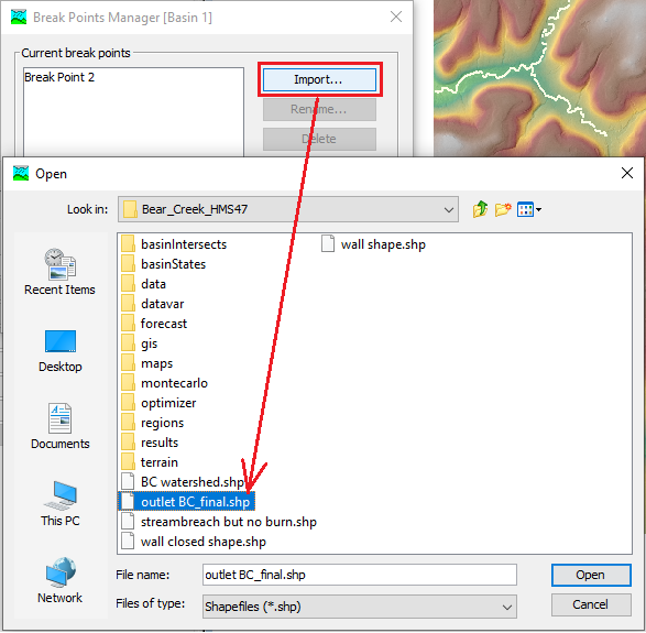
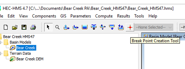
- Now in order to delineate a watershed, you will need to specify an outlet point location (Break Point, point of analysis) and this point needs to be right on top of the pixels of the streams identified at Step 6. If you already have this point defined in a shapefile, you can import it directly by opening Break Points Manager (Figure 7A), or you will need to add it manually: zoom in to the streams to add the outlet point exactly. The tool of adding outlet point is called Break Point Creation Tool at the menu icon panel on the top (Figure 7B).
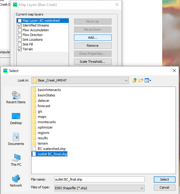
- To aid adding the break point manually, you can add the final outlet point shapefile outlet BC_final.shp as a reference. To do so, click top menu of View, then Map Layers…, and then Add… (Figure 8). You can add any other shapefile or raster file under Map Layers… window, as long as these files have the same coordinate system as terrain data or basin model. You can also turn on or turn off any other layers/files under Map Layers… window to make the basin map view window clean and fitting your needs.
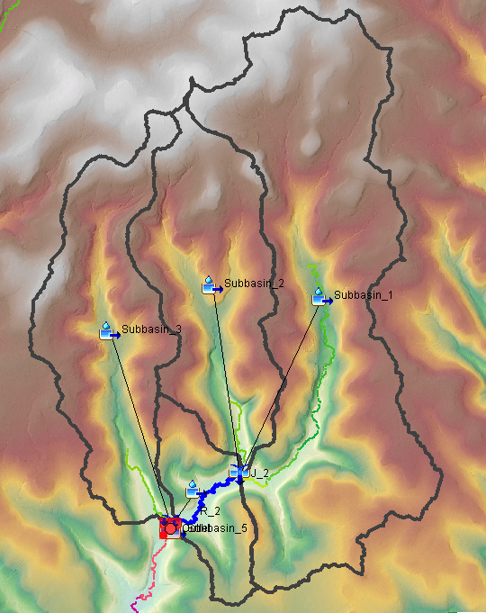
- Click top menu of GIS, then Delineate Elements to create subbasins and reaches for HEC-HMS basin model. A Delineate Elements Options dialog will open with options for setting prefixes for the element names. Choose “Subbasin_” for subbasin elements, “Reach_” for reach elements, and “J_” for junction elements (make sure the Insert Junctions option is set to Yes). Finally, set the Convert Break Points option to Yes. This option will automatically assign computation points to the break points. Click the Delineate button. Subbasins, reaches, and junctions will be generated and automatically assigned names (Figure 9). Five subbasins and two reaches are delineated in this example (Subbasin_1 to Subbasin_5 and R_1 to R_2, while Subbasin_5 is a very small subbasin near the outlet point, not easy to find on Figure 9).
After the subbasins and reaches are delineated at Step 9, click top menu of Parameters, then Characteristics —> Subbasin and Reach to calculate subbasin and reach characteristics parameters such as subbasin longest flowpath length, longest flowpath slope, and reach sinuosity. Make sure the filter set as “None” to calculate and display all subbasins and reaches.
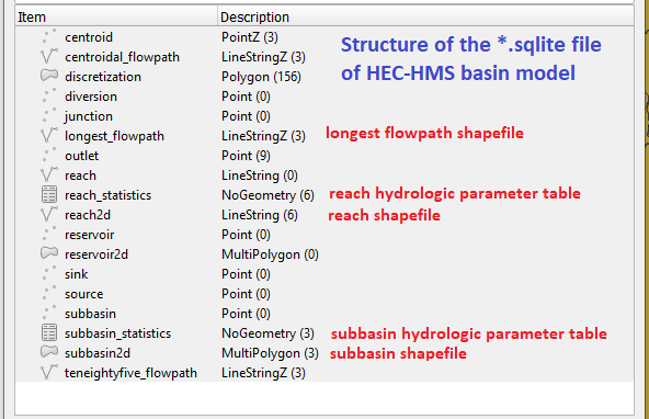
After a watershed is delineated and its parameters are calculated in HEC-HMS, all the relevant data and geometries are saved in a *.sqlite file automatically located under the HMS project file folder (Figure 10). The *.sqlite file share the same name as the basin model it represents.
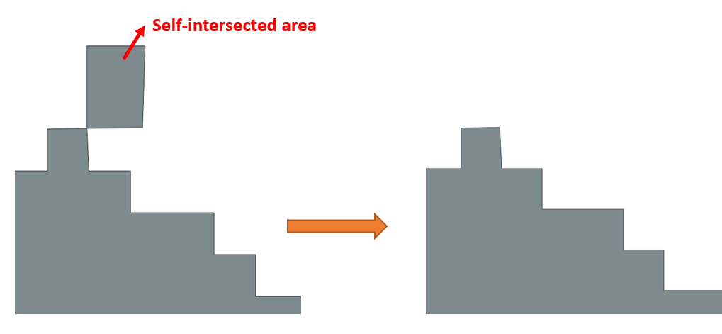
If needed, the delineated subbasin boundary can be revised by editing the “subbasin2d” polygon in *.sqlite using external GIS tools. For example, a subbasin polygon may have a “self-intersected” region and usually it is desirable to remove the abnormal area (Figure 11). After the “subbasin2d” polygon is edited, save the changes in *.sqlite. Next time when loading the HEC-HMS project file, the new boundary will show up as revised.
Leave a Reply