Create a River Channel Surface Using Cross Section Survey Data in HEC-RAS
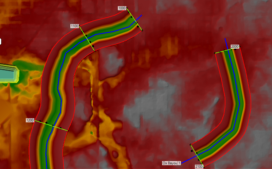
In HEC-RAS 2D, the terrain created from LiDAR DEM often does not have enough details for areas located within a river channel. For better modeling purpose, normally a river bathymetry survey is ordered to supplement LiDAR DEM in the channel areas. In addition to cross sections, it is beneficial to require the surveyor to survey a river centerline and submit it in CAD or shapefile format. The surveyed cross sections can be imported into HEC-RAS to create a new channel surface tif file to supplement the LiDAR DEM (Figure 1).
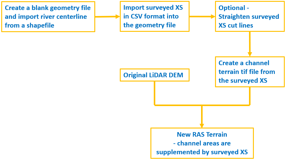
If the surveyed data including CAD and GIS files is provided in ground (surface) coordinates but the HEC-RAS model is to be established in grid coordinates, all the survey files should be converted to grid coordinates first.
After the ground to grid coordinate conversion is done, two files are to be prepared in advance:
- Prepare a CSV file which should generally be in the format as shown in Figure 2. In this example, totally 6 cross sections for two rivers are tabulated together: Bear Creek Reach 1 (4 cross sections surveyed) and Ox Bayou Reach 1 (2 cross sections surveyed).
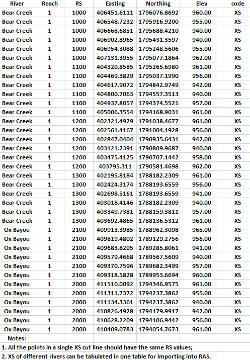
- Prepare a river centerline shapefile. The shapefile can come from survey or NHD flowlines, or it can be delineated using GIS or CAD tools. The centerline should be long enough to cover all the cross sections to be imported.
Open RAS Mapper and create a new blank geometry file – xs_from_survey_6 in this example. Enable “edit” mode of the new geometry file and import the river centerline shapefile (Figure 3). Rename the centerline’s River and Reach in Rivers – Layer Properties window to match those in the CSV file (Figure 4). Exit the “edit” mode, save the change, and close RAS Mapper.
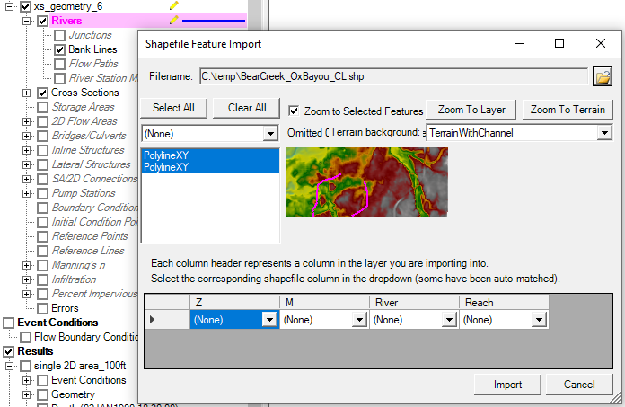
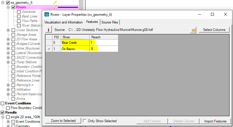
Open the geometry file in Geometry Editor window, import the cross section CSV file prepared previously (Figure 5), and click “OK” button to go to the next steps (Figure 6).

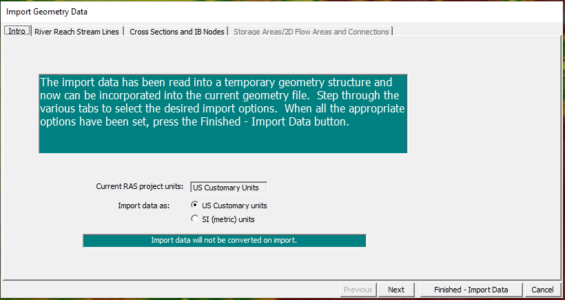
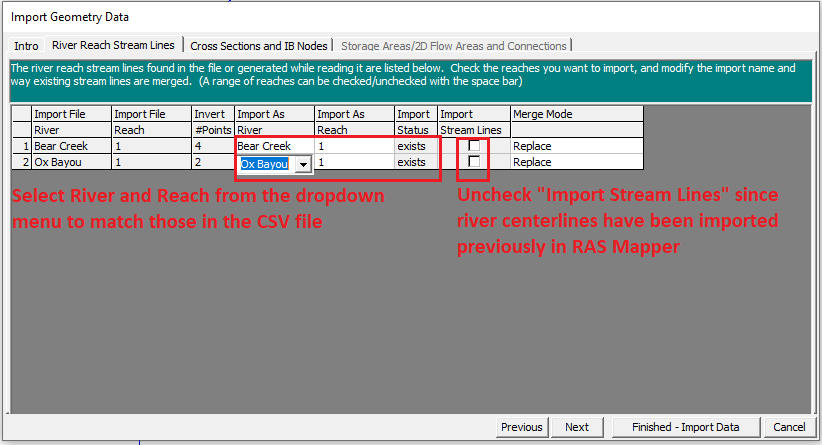
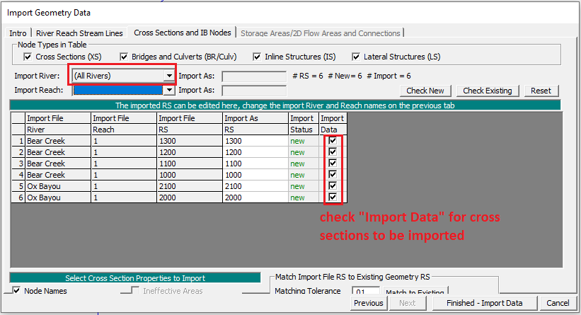
Under the “River Reach Stream Lines” tab, uncheck “Import Stream Lines” (Figure 7). Under “Cross Sections and IB Nodes” tab, make sure all RS are selected under “Import Data” column (Figure 8). Finally, click “Finished – Import Data” button to complete importing.
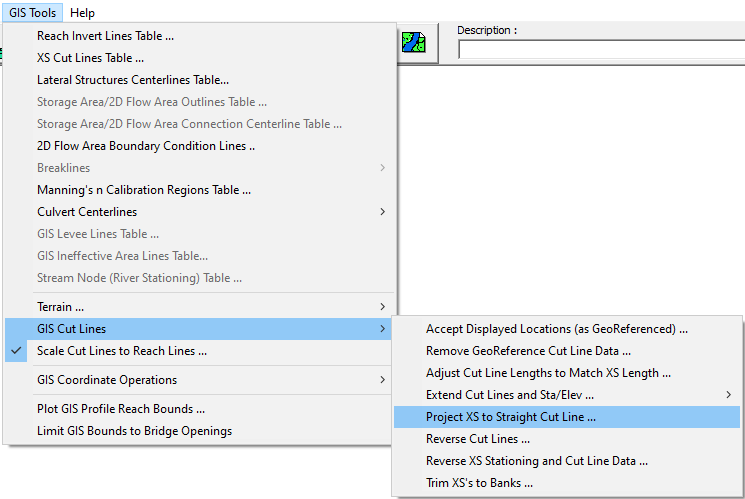
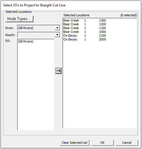
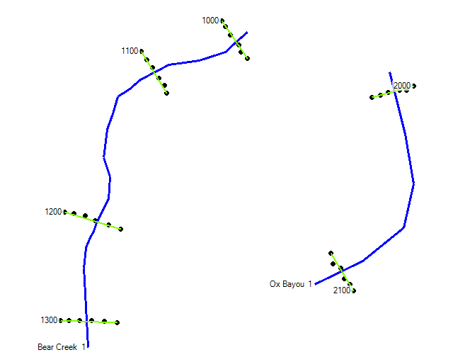
It is quite often that the survey points in a cross section cut line are not aligned as a straight line, which can be fixed by GIS Tools —>GIS Cut Lines —>Project XS to Straight Cut Line … (Figure 9 and Figure 10). To view the straightened cross section cut lines, save the changes and then go to RAS Mapper (Figure 11) or close/re-open the Geometry Editor Window.
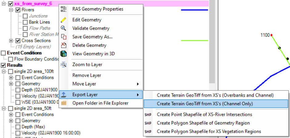
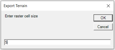
Close the Geometry Editor window and open RAS Mapper. Highlight and right click the geometry, and choose Export Layer —>Create Terrain GeoTiff from XS’s (Channel Only) (Figure 12). Provide raster cell size upon request (Figure 13) and save the exported XS terrain as a tif raster file.
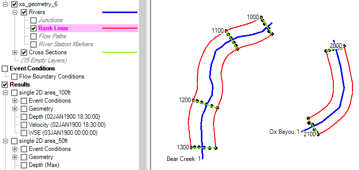
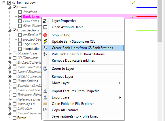
Two bank lines will be generated automatically for each river centerline in RAS Mapper after exporting the XS terrain tif file. To take a a look at them, check on and highlight “Bank Lines” under Rivers in the geometry tree (Figure 14). If the bank lines need to be updated or generated manually, enable “edit” mode of the geometry and right click “Bank Lines” —> Create Bank Lines from XS Bank Stations as indicated in Figure 15.
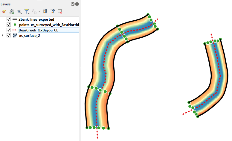
The exported tif file can be loaded to GIS for review (Figure 16). If needed, this tif file can be further clipped to a more desirable channel area boundary.
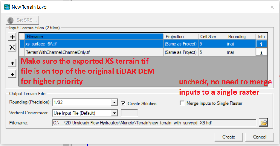
To create a new RAS Terrain file, add the exported XS terrain tif raster file on top of the original LiDAR DEM so the new RAS terrain takes the elevations of the new XS terrain for the channel area (Figure 17 and Figure 18).
Leave a Reply