Use ESRI Grid (*.asc) File to Generate XPSWMM DTM File (*.xptin)
To perform 2D modeling using XPSWMM, a surface dtm file (*.xptin) needs to be generate first in XPSWMM. Another option to create a 2D surface is Reference a Grid File which loads an existing grid file (*.asc, *.flt, *.txt) into XPSWMM, and no *.xptin file is generated. Even though a surface dtm file (*.xptin) can be generated in XPSWMM by reading XYZ files and Grid files, this post illustrates the steps to create a XPSWMM DTM file (*.xptin) from a Grid file (*.asc, converted from LiDAR DEM *.tif).
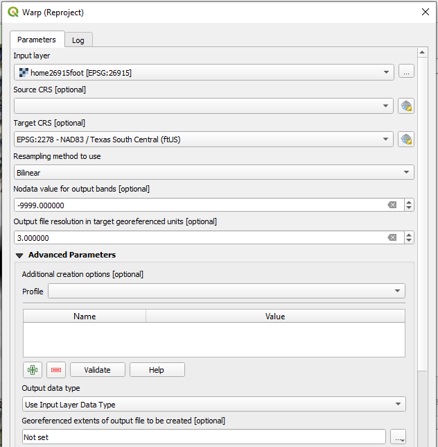
First, download a LiDAR DEM file for the project area and re-project it as needed to the desired CRS using Warp tool in QGIS (Figure 1). If the LiDAR DEM elevation unit is meter while your project requires elevation to be in foot, using Raster Calculator to convert meter to foot by a factor of 3.28084.
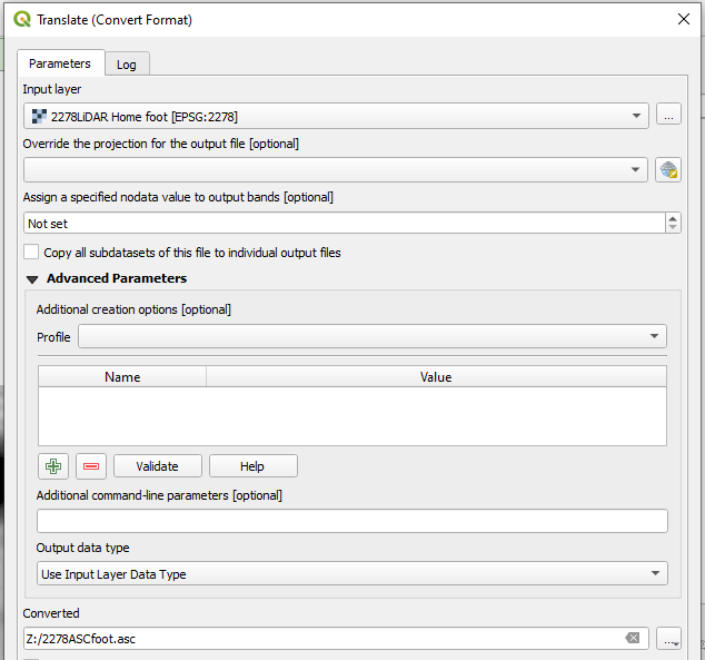
Clip the re-projected LiDAR DEM file (*.tif) to the project area and convert the clipped file (*.tif) to ERSI Grid format (*.asc) using QGIS raster tool of Translate (Convert Format) (Figure 2).
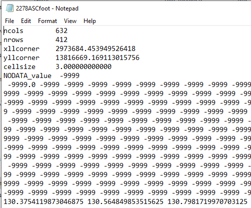
A *.asc file can be opened by Notepad (text editor) and its file structure is shown in Figure 3.
where
ncolsandnrowsare the numbers of columns and rowsxllcorneris the western (left) coordinate of x andyllcorneris southern (bottom) coordinate of y- when the data points are cell-centered
xllcenterandyllcenterare used instead ofxllcornerandyllcorner cellsizeis the side length of a square cell- NODATA_value is the value that is regarded as “N/A” or “not applicable”; this line is optional
- The remainder of the file shows the raster value of each cell starting from the northwestern (upper left) corner.
- Typically a *.asc file is accompanied by a “.prj” file of the same name that defines the CRS (coordinate reference system) used in the header
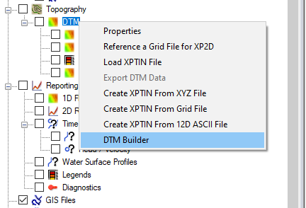
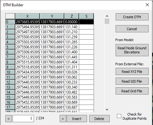
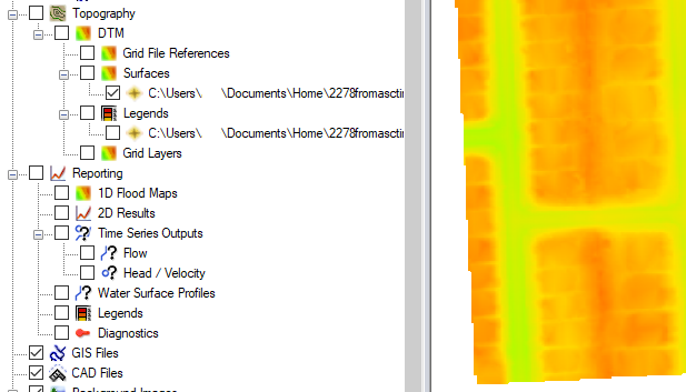
A *.asc grid file can be read into XPSWMM by “Create XPTIN From Grid File” or “DTM Builder” (Figure 4) after right clicking Topography—>DTM in the layer panel. It is recommended to click “DTM Builder” to create a *.xptin file since using “DTM Builder” allows you to edit the *.asc file before applying.
Click to open “DTM Builder“, and load *.asc by clicking the button of “Read Grid File” (Figure 5). As shown in Figure 5, in this example, the Row 0 has elevation Z=0.00000 which is an error. Highlight the Row 0 and click the button of “Delete” to delete this row from the data set. Column S is to define break lines where consecutive rows with the same numbers in column S are break lines (ridges or gullies). In Figure 5, no break lines are defined. Finally, click “Create DTM” to generate a *.xptin file (Figure 6).
Leave a Reply