GIS Shapefile, Microstation DGN File, and Combined Scale Factor
Combined scale factor (CSF) is introduced in this post as well as the difference between ground coordinates (surface coordinates) and grid coordinates. As explained in the post, in a GIS environment, normally shapefiles or raster files are in a projected coordinate system in reference to grid coordinates, while an engineering design or survey CAD file is usually in a state plane coordinate system using ground coordinates (surface coordinates).
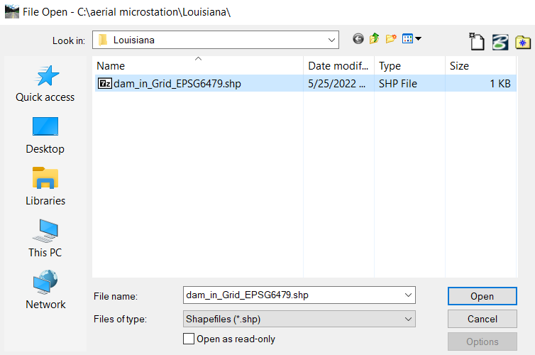
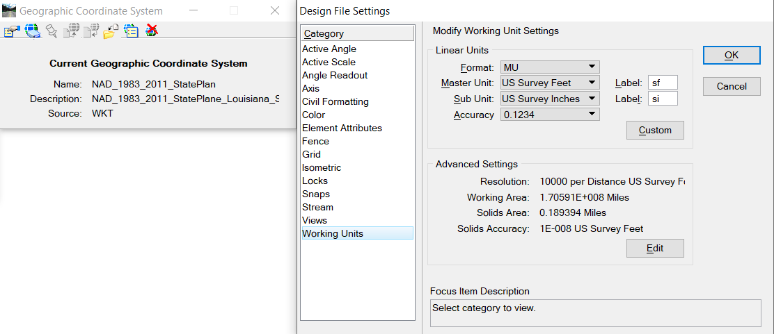
MicroStation can open a shapefile defined in a projected coordinate system (Figure 1) and then save the shapefile as a dgn file. The newly saved dgn file should inherit the shapefile’s coordinate system and units (Figure 2). However, due to the shapefile is in grid coordinates, if the design project requires CAD files in ground coordinates, the newly saved dgn file needs to be converted to another dgn file in ground coordinates.
Make a copy of the new dgn file saved from the shapefile and select/delete all elements in it to make it a blank file. This blank dgn file keeps the geographic coordinate system and working unit settings and is to be used as the master file with ground coordinates.
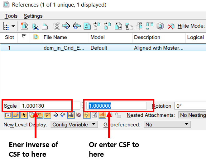
Attach the dgn file saved from the shapefile to the blank master file. In MicroStation References Manager window, enter CSF or its inverse as illustrated in Figure 3 to scale up or scale down the grid coordinate of the reference file to its ground counterpart.
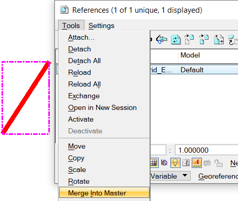
Merge the reference file to the blank master file (Figure 4). The blank master file now becomes a dgn file with ground coordinates after merging. Back check the new ground coordinate dgn file by comparing the coordinate values of a vertex point with those on grid coordinate dgn file: The grid coordinates should be equal to ground coordinates X CSF.
Another way to open and save a shapefile to a dgn file in ground coordinates is to convert the shapefile (normally in grid coordinates such as state plane coordinate systems) to a new shapefile in ground coordinates, which requires the users to define a customized coordinate reference system (CRS) using ground coordinates.
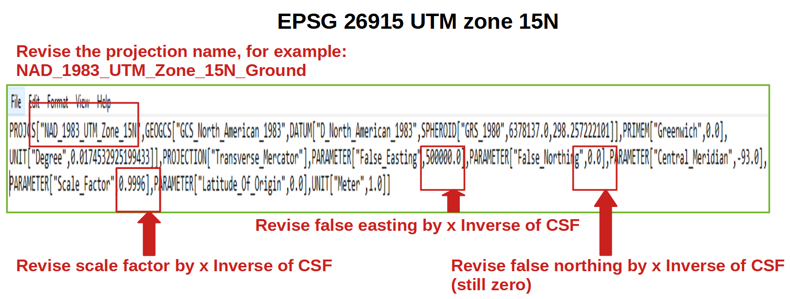
For UTM zones using Transverse Mercator projection, to define a new CRS using ground coordinates, obtain the UTM CRS *.prj file (WKT format, in grid coordinate system) from your project files or download one from https://spatialreference.org/. Open the *.prj file in WKT format (in this example it is the EPSG 26915 UTM Zone 15N *.prj file), and revise the following 3 parameters (Figure 5) and save it as another *.prj file (credit to Melita Kennedy):
- The new False_Easting is to be calculated as the original False_Easting / CSF, or x Inverse of CSF;
- The new False_Northing is to be calculated as the original False_Northing / CSF, or x Inverse of CSF;
- The new Scale_Factor is to be calculated as the original Scale_Factor / CSF, or x Inverse of CSF.
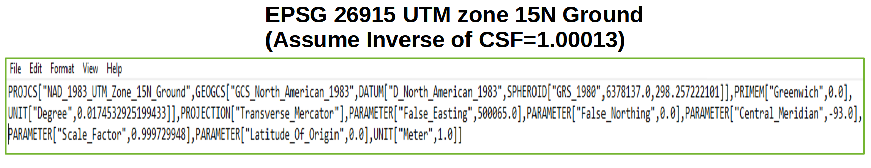
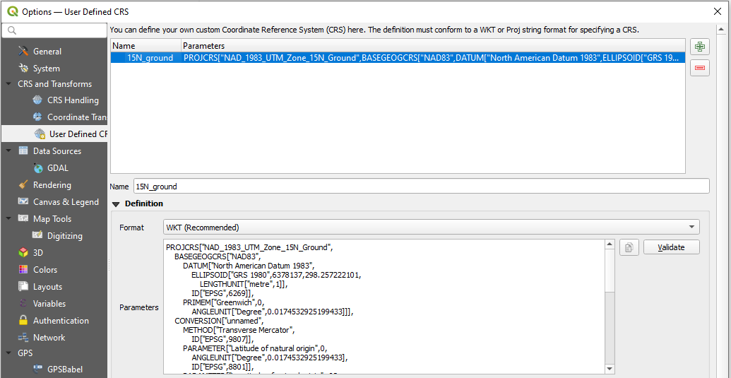
The newly saved *.prj file (Figure 6) can be imported to QGIS (Figure 7) or ArcGIS as a customized CRS of ground coordinates. Re-project a normal shapefile in grid coordinates to this customized CRS to get a new shapefile in ground coordinates. Now when opening the re-projected shapefile and saving it as a dgn file in MicroStation, you will get a dgn file in ground coordinates directly.
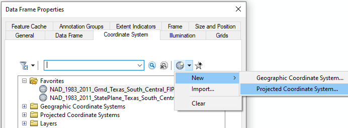
To create a state plane coordinate system (SPCS) in Lambert Conformal Conic (LCC) projection using ground coordinates in ArcGIS, define a new custom CRS: open the the Data Frame Properties window and under the Coordinate System Tab click New —> Projected Coordinate System (Figure 8). Assign a name to the new CRS and choose Lambert_Conformal_Conic as your projection name (Figure 9).
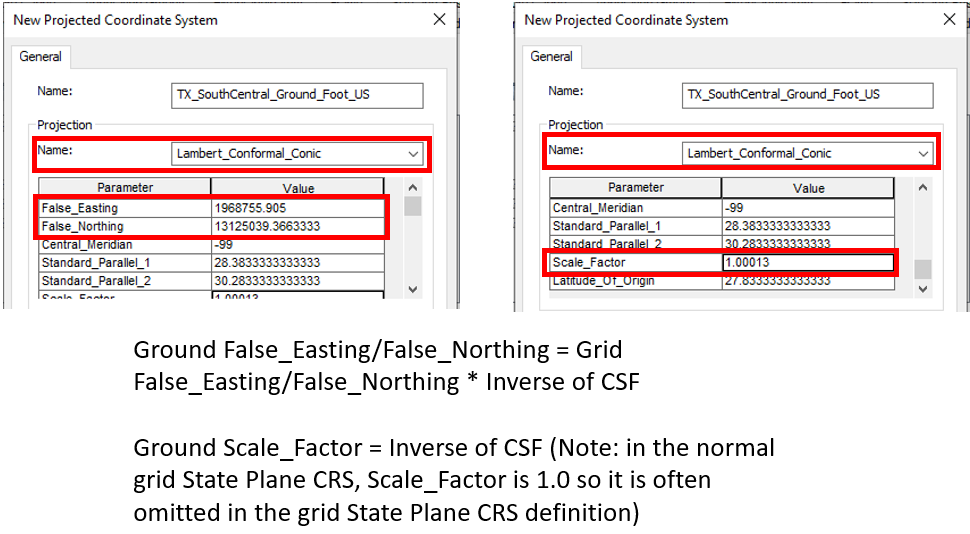
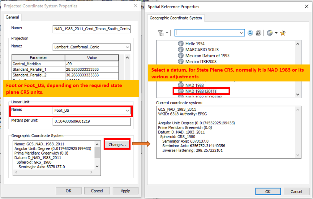
In the Parameter – Value table, all parameters use the same values as the normal grid state plane coordinate CRS with exceptions of False_Easting, False_Northing, and Scale_Factor (Figure 9). The new CRS unit and Geographic Coordinate System (Datum) definition should be set as the same values of the original grid state plane coordinate system (Figure 10).
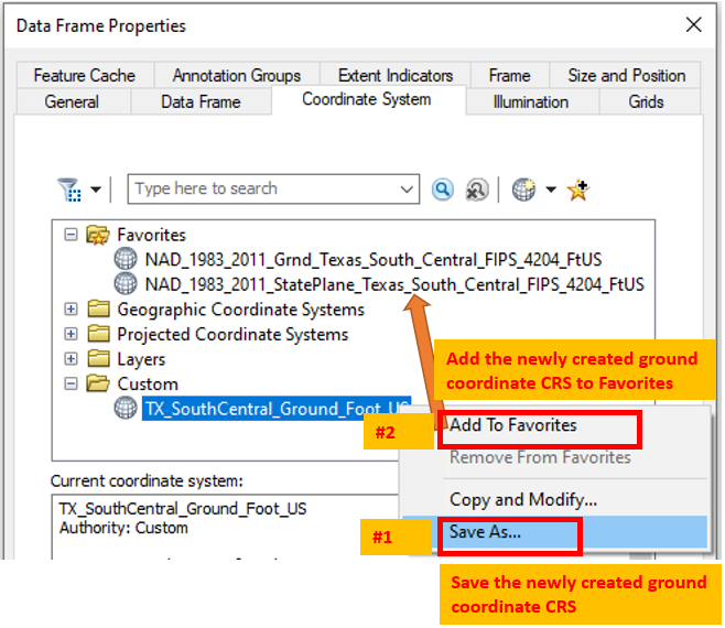
Finally save the newly created ground coordinate CRS and add it to Favorites (Figure 11).
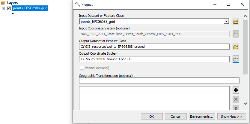
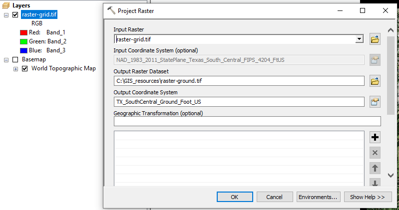
Now a shapefile or raster file in grid coordinates CRS can be re-projected to the new ground coordinate CRS (Figure 12 and Figure 13).
The detailed explanation on creating a custom CRS in ground coordinates (surface coordinates) can also be found here or here or here (again, credit to Melita Kennedy).
Leave a Reply