Grid Coordinate, Ground Coordinate, Distance, Combined Scale Factor
The earth surface is irregular and curvy. To describe the earth surface mathematically, an ellipsoid is defined to approximate the bumpy earth surface, or more accurately a datum based on an ellipsoid – Geographic Coordinate System. To further represent a point on an ellipsoid (3D surface) on 2D maps, we use various projection methods to make the conversion and the converted 2D surface (grid plane) with its coordinate definition is a Projected Coordinate System. Refer to this post for more details about ellipsoid, datum, and coordinate reference system (CRS).
The distance between two points on the earth surface can be measured in three different ways depending on which reference surface (or grid plane) is used as shown in Figure 1: ground distance or horizontal distance, ellipsoid distance, and grid distance. The combined scale factor (CSF) is usually used to convert a ground distance to grid distance which is the product of elevation scale factor (ESF) and grid scale factor (GSF).
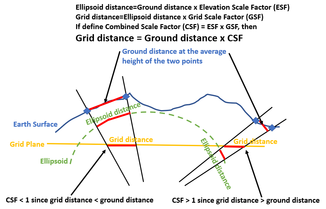
Combined scale factor (CSF) can be greater or less than 1.0 depending on the relationship between ground distance and grid distance as illustrated in Figure 1. CSF is usually provided by a professional surveyor and it varies with geographic locations and projects, although some government agencies provide a table to list the recommended/commonly used CSF for different areas within their jurisdictions. It should be noted that a surveyor may provide the inverse of the above CSF but still call it as CSF. It is up to project engineers to ensure a correct interpretation of any supplied CSF.
A point’s northing/easting (X, Y) coordinates in a projected coordinate system are the distances between this point and the origin (0,0) measured along X and Y directions. For this reason, a point’s northing/easting can have different values depending on which distances are measured: ground distance (surface distance) or grid distance (Figure 2). If the coordinates are based on grid distances, they are on a grid coordinate system; on the other hand if the coordinates are measured by ground distances, they are on a ground coordinate system (surface coordinate system).
Normally in a GIS environment, the shapefiles or raster files in a projected coordinate system are on a grid coordinate system, such as Texas State Plane Coordinate System FIPS 4201 to 4205, or Louisiana State Plane Coordinate System FIPS 1701 and 1702, which means, for example, the length of a line feature in a linear type shapefile is measured by grid distance. It is uncommon, but sometimes for convenience purpose, a user can define a customized state plane coordinate system using ground coordinates (surface coordinates) by revising its grid coordinate system *.prj file (refer to this post for more details).
For engineering design, such as a transportation project of TxDOT, the CAD files (survey, topo, plans) are required to use ground coordinates of a state plane coordinate system. It is important to 1, check the design or survey files from different sources are in a grid or a ground coordinate system; 2, convert the files from one coordinate system to the other coordinate system as needed.
Since an aerial image (a raster file) is usually in a projected coordinate system using grid coordinates or to be projected to such a grid coordinate system, while an engineering design or survey CAD file is usually in a projected coordinate system using ground coordinates, CSF is needed when attaching a background aerial image to a CAD design or survey file.
Suppose you have a design CAD file denoting top of dam alignment in ground coordinates and you want to download a background aerial image to attach to the CAD file.
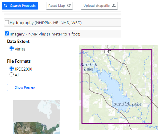
First download the aerial image of the project area. In this example, NAIP Plus Imagery from USGS National Map website is downloaded (Figure 3) and it is in EPSG 3857, a geographic coordinate system (Figure 4).
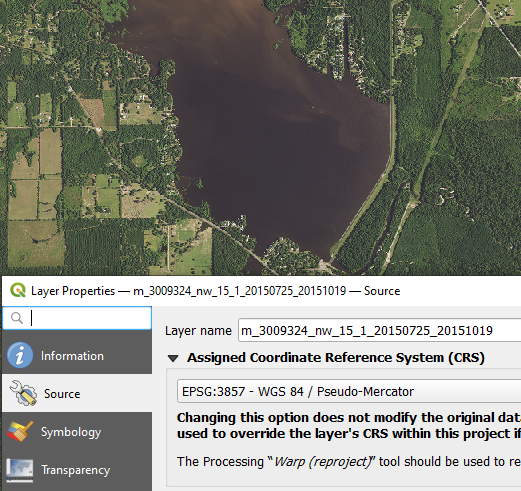
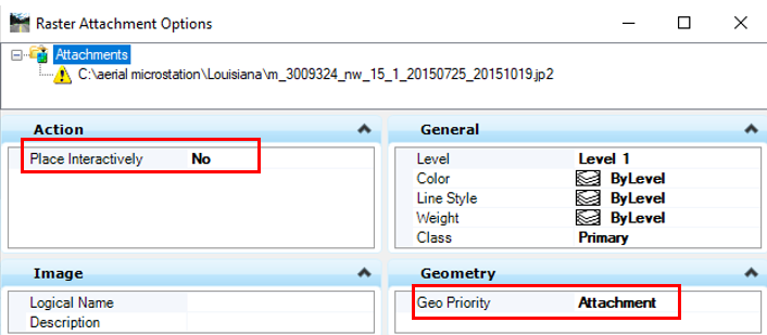
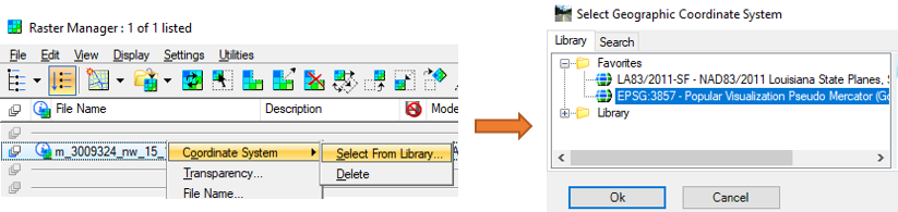
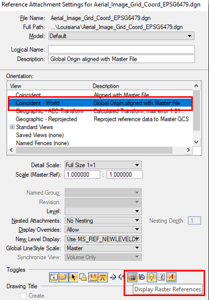
Next create a blank MicroStation dgn file as the aerial image container (working unit: survey feet since the project is to be done in Louisiana State Plane Coordinate System South Zone in this example) and attach the aerial downloaded (Figure 5). After attaching, set the aerial image to its original coordinate system and in this example, it is EPSG 3857 (Figure 6).
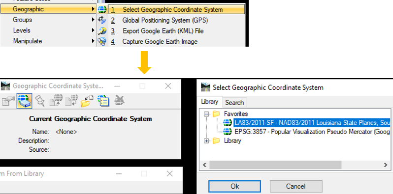
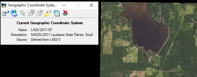
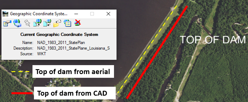
Now, the MicroStation image container file’s coordinate system needs to be set to the required design projection system, in this case Louisiana State Plane Coordinate System South Zone. Open Tools from the top menu and click Geographic —> Select Geographic Coordinate System in MicroStation (Figure 7). Note this step is different from Figure 6: in Figure 6, you are assigning the original coordinate system of the aerial image, and in Figure 7, you are setting the MicroStation container file coordinate system so that MicroStation can automatically re-project the aerial image to the required engineering design coordinate system (most likely it is a state plane coordinate system). The new coordinate system name will show up in Figure 8.
Open the design CAD file in ground coordinates and ensure the file’s geographic coordinate system is set up correctly (in this example, it is Louisiana State Plane Coordinate System South Zone, refer to Figure 7). Attach the image container dgn file (Figure 9) and you will find that the line is not lining up with the aerial image (Figure 10).
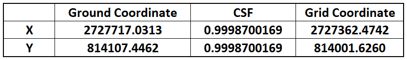
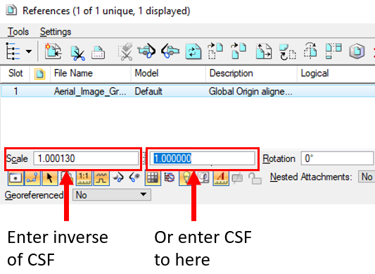
The reason that the CAD file does not line up with the aerial image is due to the fact the CAD file (as master file) is in ground coordinate while the aerial image container file (as reference file) is in grid coordinates. An easy way to fix the problem is to enter CSF or its inverse when the aerial container file is attached to the CAD design file as show in Figure 11. The example CSF in Figure 11 is 0.9998700169 and its inverse is 1.00013.
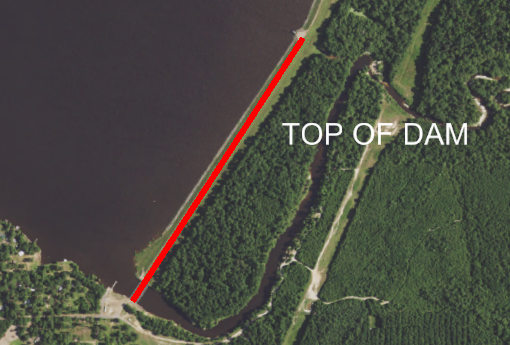
After adjusting the scale factor in Figure 11, the CAD line work is showing up correctly in Figure 12.
A similar process can be implemented to attach a CAD file in ground coordinates (as reference file) to another CAD file in grid coordinate system (as master file) by adjusting the scale factor as shown in Figure 11 via CSF or its inverse.
Leave a Reply