Bridge Pier and Abutment Scour Countermeasure Riprap Design by FHWA Hydraulic Toolbox
Hydraulic Toolbox is a powerful tool to design riprap protection for channel banks, culvert outlets, and bridge scour countermeasures. This post is to focus on bridge pier and abutment scour countermeasure riprap design and there is another post for channel revetment and culvert outlet protection design.
Per FHWA HEC-18, the bridge scour countermeasure design should be based on a more severe flood event than its scour design flood event so the designed countermeasures are still stable under floods larger than those associated with the scour design flood frequency (Table 1).

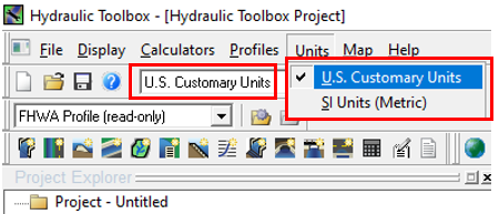
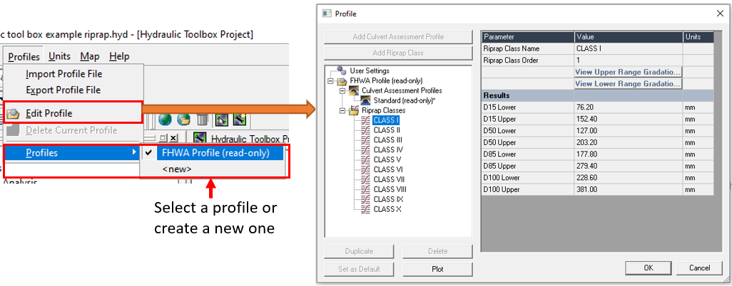
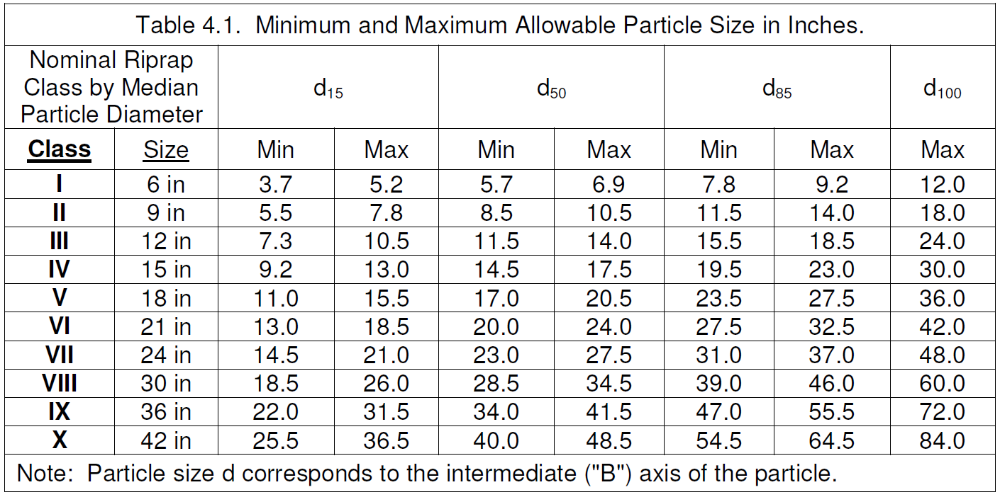
After launching the program, you may fist want to check the unit setting (Figure 1). Next, open the default profile (FHWA Profile) to ensure the riprap class gradations meet the project needs (Figure 2A) or create a new profile with customized riprap gradations approved by clients (Figure 2B showings HEC-23 Table 4.1 gradation).
Riprap Analysis – Bridge Pier
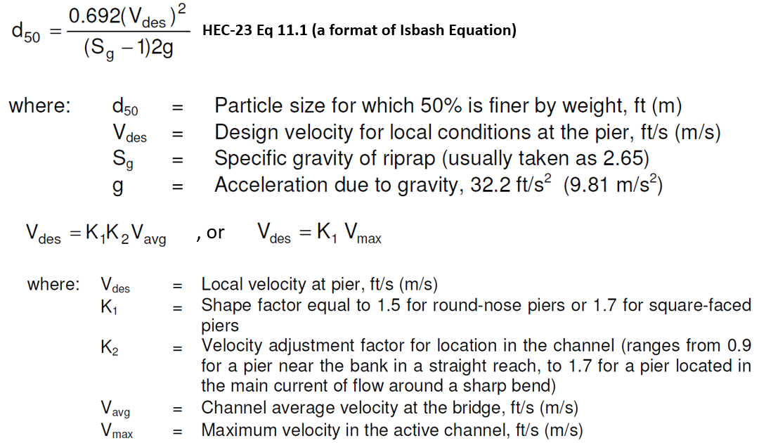
Hydraulic Toolbox adopted HEC-23 Volume 2 Design Guideline 11 Equation 11.1 (Figure 3) for bridge pier riprap design. It is important to note that the velocity used in Equation 11.1 should be representative of the conditions in the immediate bridge pier vicinity including the constriction caused by the bridge (suggestion: use average velocity at HEC-RAS Bridge XS BR U or BR D, whichever is more constrictive).
After performing a successful HEC-RAS bridge model run and bridge scour calculation, open Hydraulic Toolbox and add a New Riprap Analysis Project – Pier to start a new bridge pier riprap protection design (Figure 4). The results include D50, riprap class, and layout dimensions(Figure 5). The riprap class is selected by comparing the D50 result with the pre-defined riprap gradations in the profile.
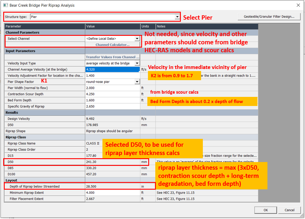
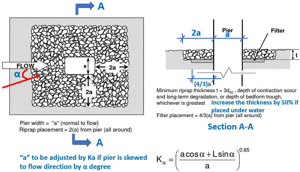
Be careful about depth of riprap below streambed (riprap layer thickness) in Figure 4: it seems the current version of Hydraulic Toolbox does not take consideration of contraction scour depth or bed form depth as required; instead, it only treats the value of 3 x D50 as the final result. This may be a bug of the software.
Riprap Analysis – Bridge Abutment
Hydraulic Toolbox adopted HEC-23 Volume 2 Design Guideline 14 Equation 14.1 and 14.2 (Figure 6) for bridge abutment riprap design.
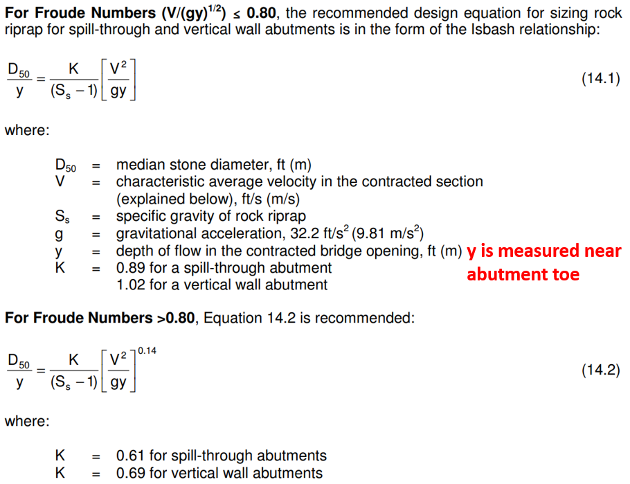
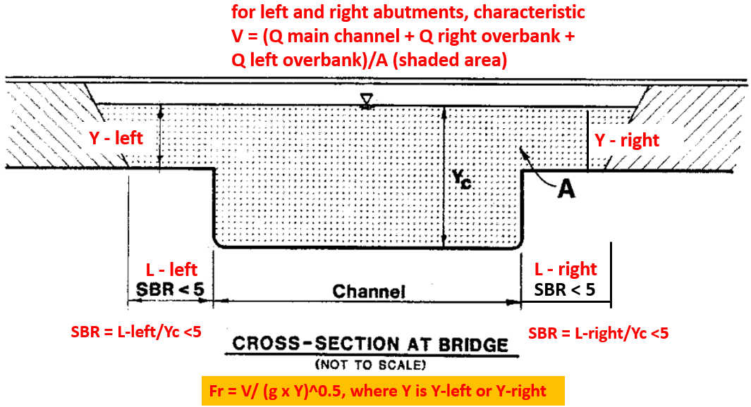
The velocity V used in Equation 14.1 and 14.2 is called characteristic velocity at the abutment toe whose value is calculated by SBR (set-back ratio) method as explained below in Figure 7, Figure 8, and Figure 9. The characteristic velocity must be hand-calculated by using Q, Y, A, W values from HEC-RAS bridge XS BR U or BR D, whichever is more restrictive.
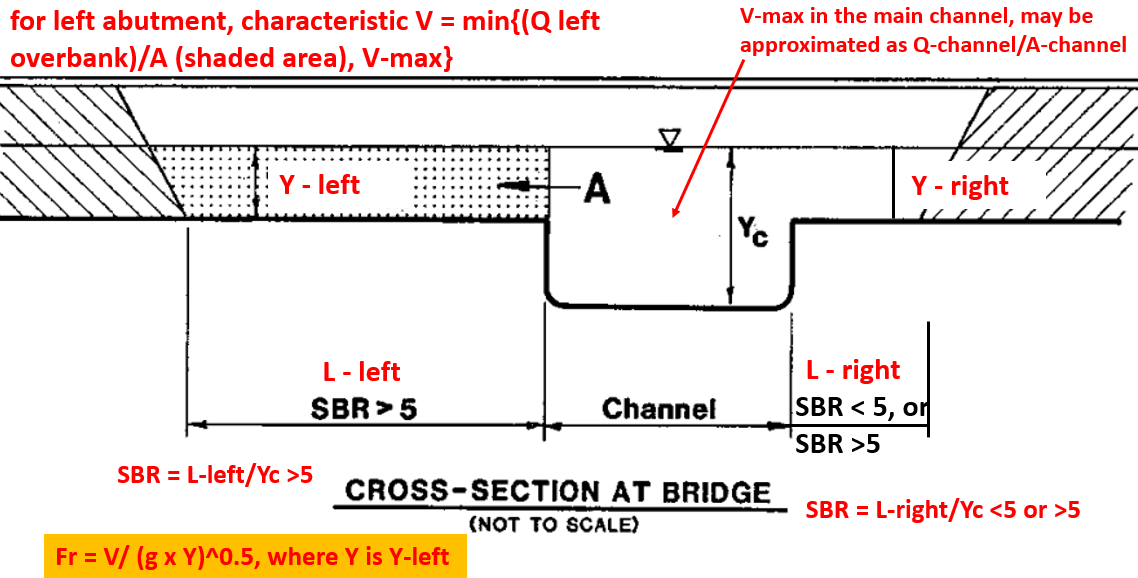
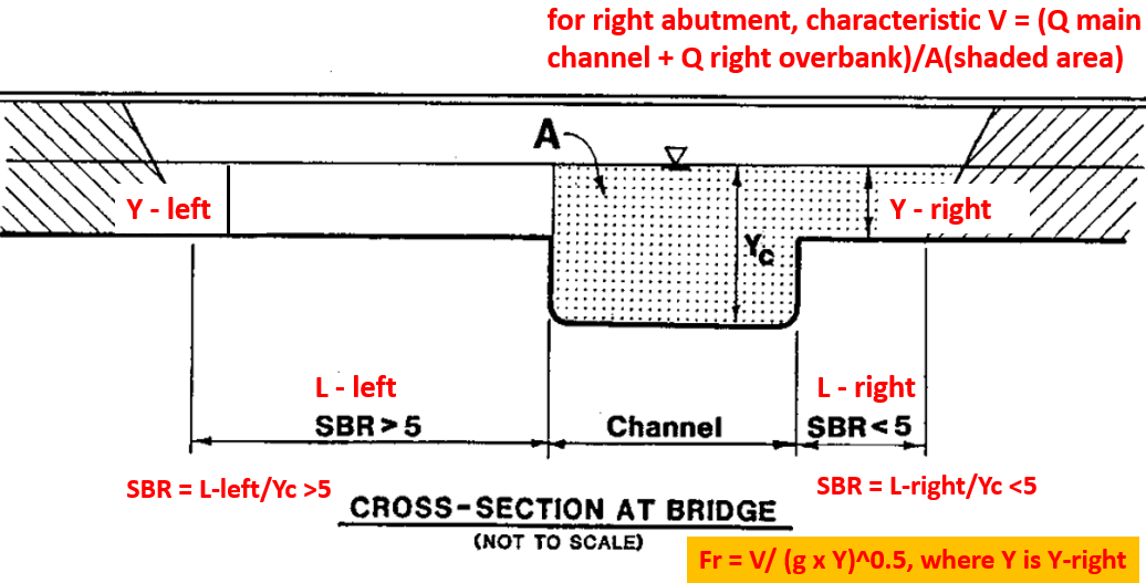
After performing a successful HEC-RAS bridge model run and bridge scour calculation, open Hydraulic Toolbox and add a New Riprap Analysis Project – Abutment to start a new bridge abutment riprap protection design (Figure 10). The results include D50, riprap class, and layout dimensions. The riprap class is selected by comparing the calculated D50 value with the pre-defined riprap classes in the profile.
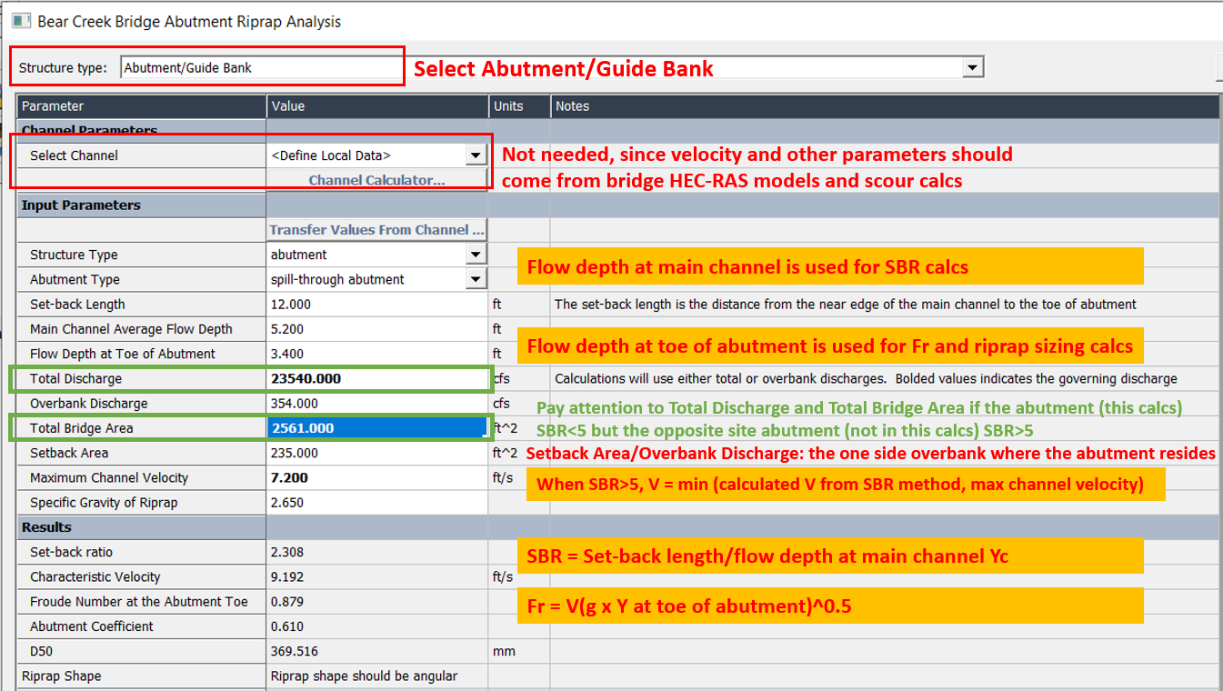
If an abutment’s SBR is less than 5 but the opposite side abutment’s SRB is greater than 5, the Total Bridge Area and the Total Discharge supplied in Figure 10 should NOT include the flow and area of the opposite side overbank (refer to Figure 9).
Pay attention to maximum channel velocity in Figure 10: it seems the current version of Hydraulic Toolbox does not compare its value with the calculated velocity from SBR method when SBR >5; instead, it only treats the SBR method velocity value as the final result for characteristic velocity. This may be a bug of the software.
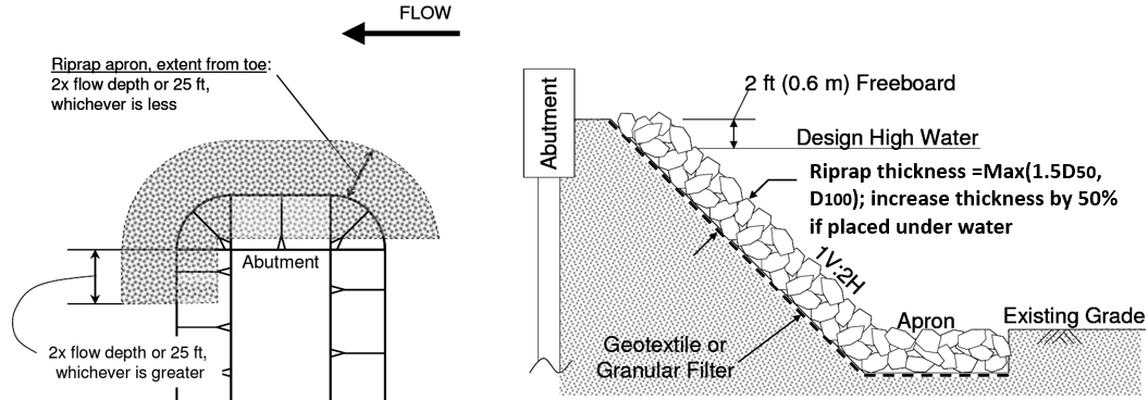
Hydraulic Toolbox abutment riprap design output includes riprap layer thickness and layout dimensions (Figure 11 and Figure 12).

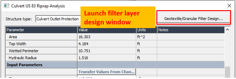
There may be a need to design a filter layer underneath the riprap to prevent the soil particles from being washed out. Hydraulic Toolbox Riprap Analysis has coded in filter layer design routine which can be launched by clicking the button on the upper right side (Figure 13). The details of geotextile and granular filter layer design by Hydraulic Toolbox can be found here (place holder for now).
1 COMMENT