Channel Revetment and Culvert Outlet Protection Riprap Design by FHWA Hydraulic Toolbox
Hydraulic Toolbox is a powerful tool to design riprap protection for channel banks, culvert outlets, and bridge scour countermeasures. A brief introduction about riprap is found here for general reference.
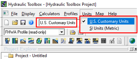
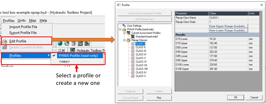
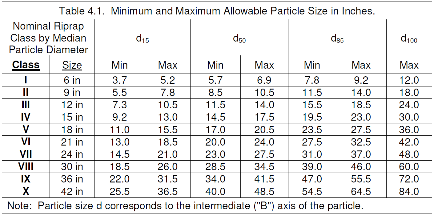
After launching the program, you may fist want to check the unit setting (Figure 1). Next, open the default profile (FHWA Profile) to ensure the riprap class gradations meet the project needs (Figure 2A) or create a new profile with customized riprap gradations approved by clients (Figure 2B showings HEC-23 Table 4.1 gradation).
Riprap Analysis – Revetment (Channel Slope =< 2%)
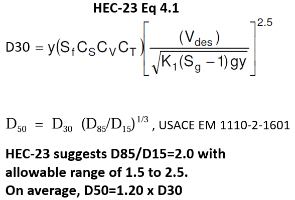
Hydraulic Toolbox adopted HEC-23 Volume 2 Design Guideline 4 Equation 4.1 (Figure 3) for channel revetment riprap design. More details about this equations can be found at HEC-23 Vol 2 Page DG4.4 or USACE EM 1110-2-1601.
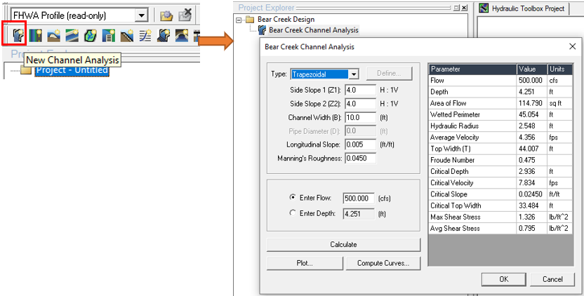
To design a channel bank riprap protection (revetment), create a New Channel Analysis project, which is basically a Manning’s Equation solver, and enter the channel geometries and the design flow (Figure 4).
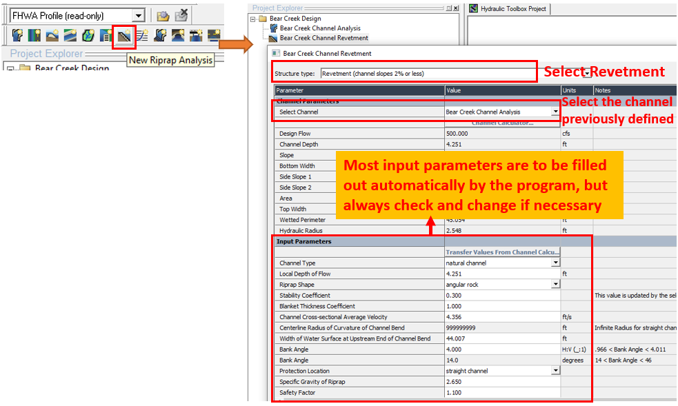
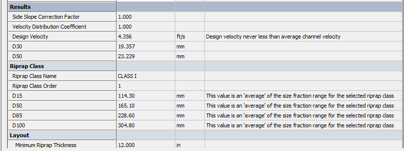
Now add a New Riprap Analysis Project – Revetment (Channel slope 2% or less), select and use the previously defined channel as inputs (Figure 5). The results including D30, D50, riprap class and thickness can be viewed in Figure 6. The riprap class is selected by comparing the D50 result with the pre-defined riprap gradations in the profile.
Riprap Analysis – Culvert Outlet Protection (Circular Culvert diameter =< 60in)
Hydraulic Toolbox adopted FHWA HEC-14 Chapter 10 Equation 10.4 (Figure 3) for small circular culvert outlet riprap apron design (Figure 4).
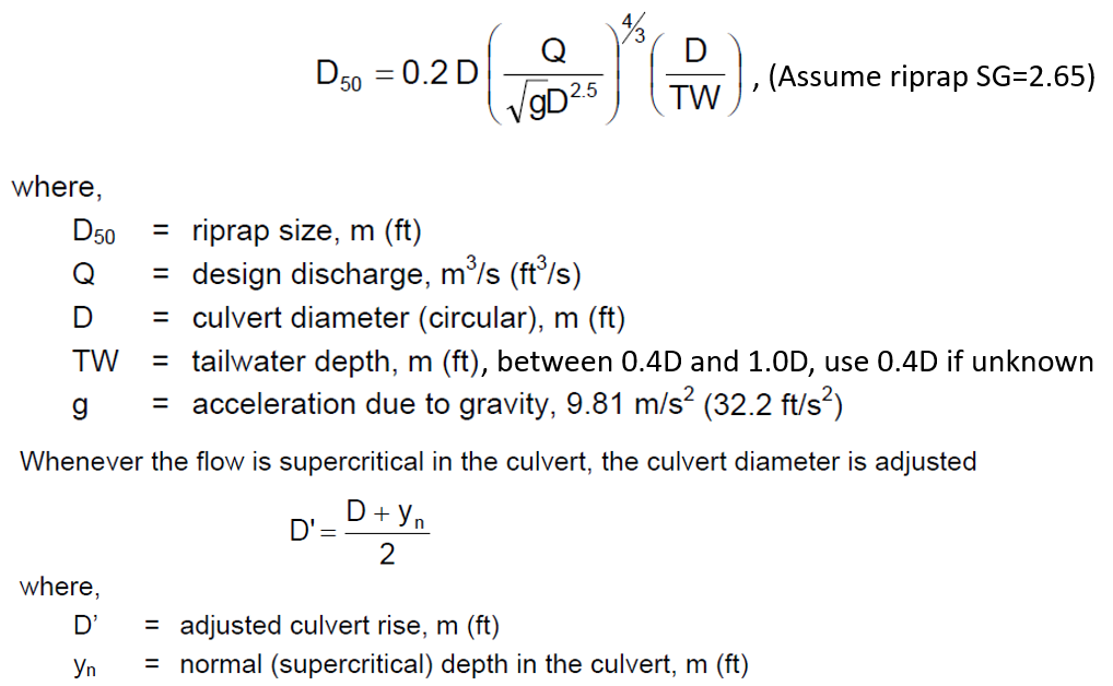
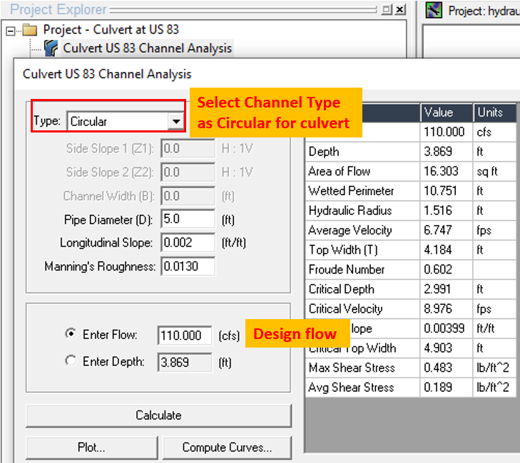
To start culvert outlet protection design, create a New Channel Analysis project and use it to define the circular culvert size, slope, and design flow (Figure 8). Additionally, if supercritical flow is present in the culvert, the normal depth value Yn is acquired from the channel analysis results.
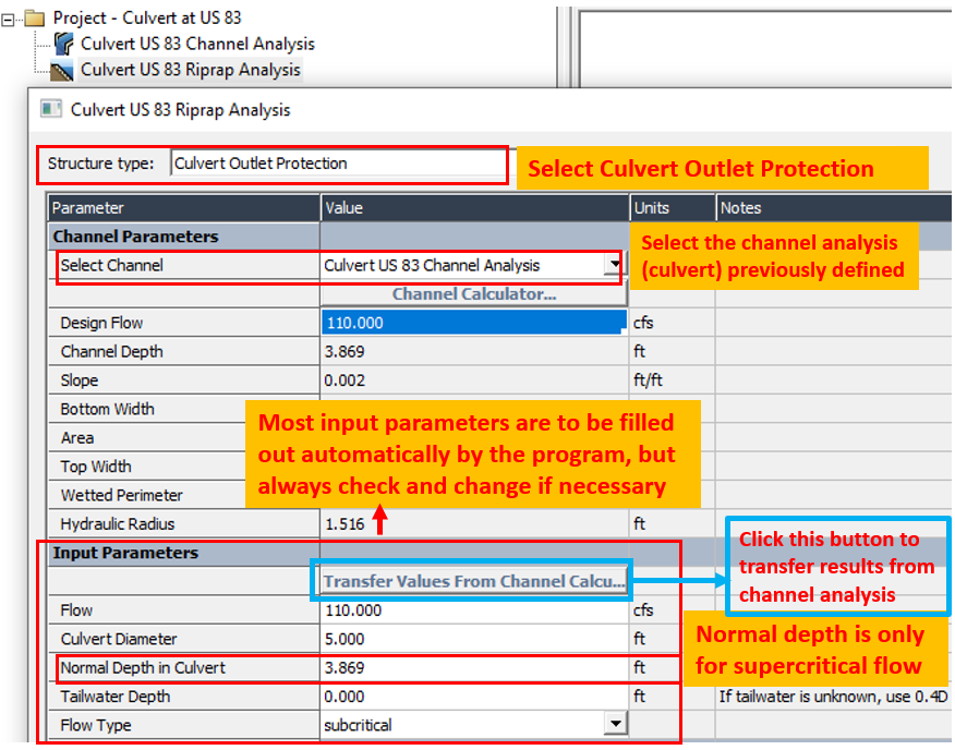
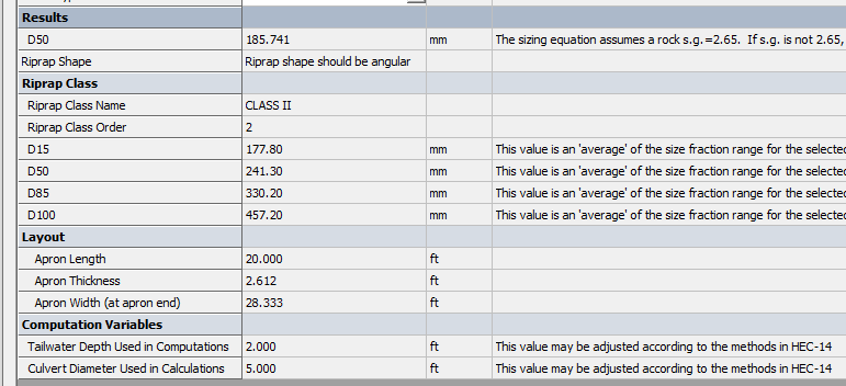
Now add a New Riprap Analysis Project – Culvert Outlet Protection, select and use the previously defined channel (circular culvert) as inputs (Figure 9). The results including D50, riprap class, apron length/width/thickness can be viewed in Figure 10. The riprap class is selected by comparing the D50 result with the pre-defined riprap gradations in the profile.
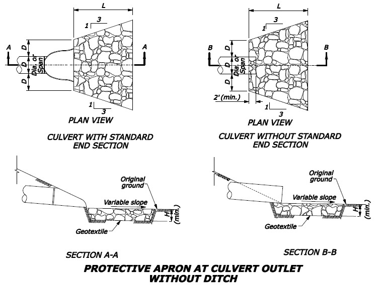
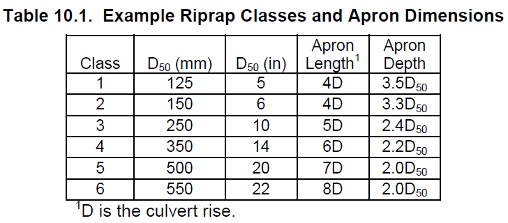
The riprap apron plan and section views are shown in Figure 11. HEC-14 provides a table for riprap apron length and depth estimate, which has been implemented in Hydraulic Toolbox.
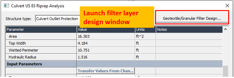
There may be a need to design a filter layer underneath the riprap to prevent the soil particles from being washed out. Hydraulic Toolbox Riprap Analysis has coded in filter layer design routine which can be launched by clicking the button on the upper right side (Figure 13). The details of geotextile and granular filter layer design by Hydraulic Toolbox can be found here (place holder for now).
1 COMMENT