Soils Layer and Infiltration Layer in HEC-RAS 6.0
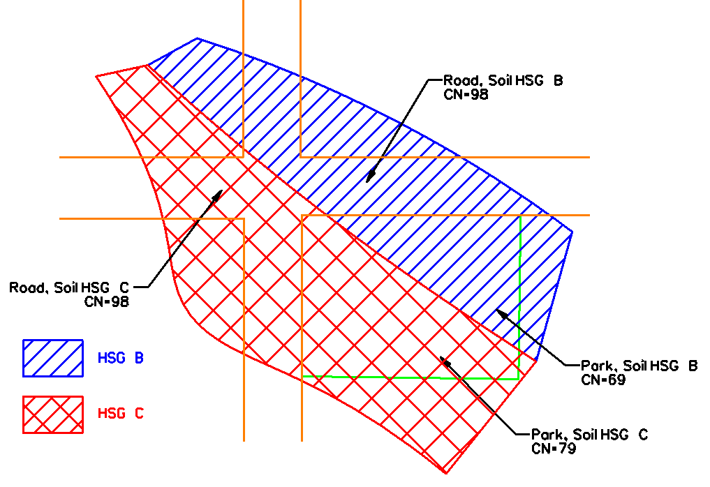
To model infiltration loss within 2D domain for a Rain-on-Grid (RoG) HEC-RAS model, a land cover layer and a soils layer needs to be generated first and then an infiltration layer will be created to assign infiltration parameters by intersecting the land cover layer and the soils layer illustrated in Figure 1. In Figure 1, SCS Curve Number is the filtration method and CN values are determined by land covers (Road & Park) and soil types (HSG B & C). Although this post will demonstrate how to intersect a land cover layer and a soils layer to get an infiltration layer, it is also an acceptable practice sometimes to create an infiltration layer simply from a land cover layer or a soils layer alone, or even from a separate shapefile, depending on the project requirements and data availability.
How to create a land cover layer in HEC-RAS 6.0 is explained in here and this post focuses on the steps to create a soils layer and an infiltration layer. Hydrologic Soil Group Data (HSG) is included in SSURGO (Soil Survey Geographic database) which is distributed by the Natural Resources Conservation Service (NRCS) of USDA. NRCS provides two ways to download an area’s SSURGO:
- Downloading SSURGO as shapefiles and tables through Web Soil Survey. Refer to this post for instruction. The downloaded shapefiles are in reference to EPSG 4326.
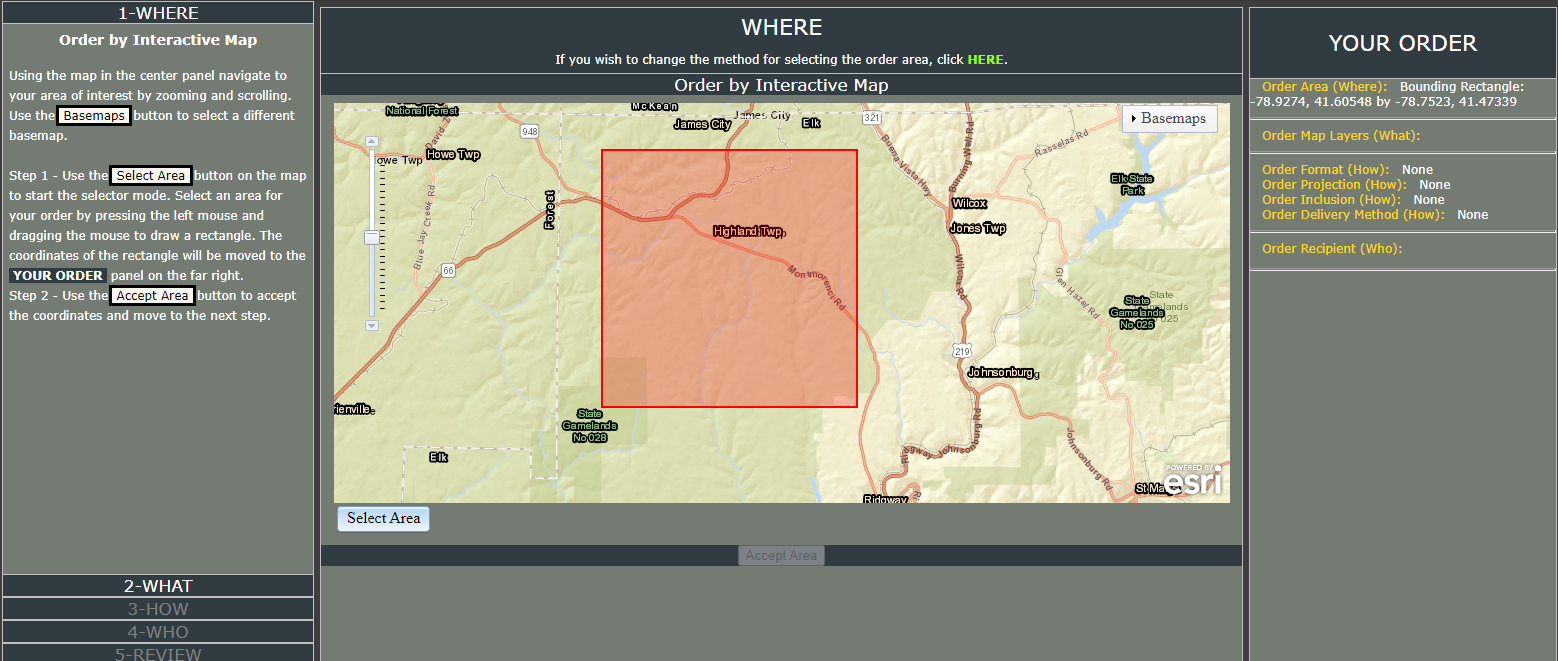
- Downloading SSURGO as a raster file (gSSURGO) in ESRI geodatabase (EPSG 5070 or ESRI 102039) through NRCS GeoSpatial Data Gateway. The drawback of downloading a gSSURGO raster file in geodatabase format is that quite often it covers an entire state (file size is big) even though you select a project area using a boundary box as shown in Figure 1.
The steps to create a soils layer is similar to those of creating a land cover layer:
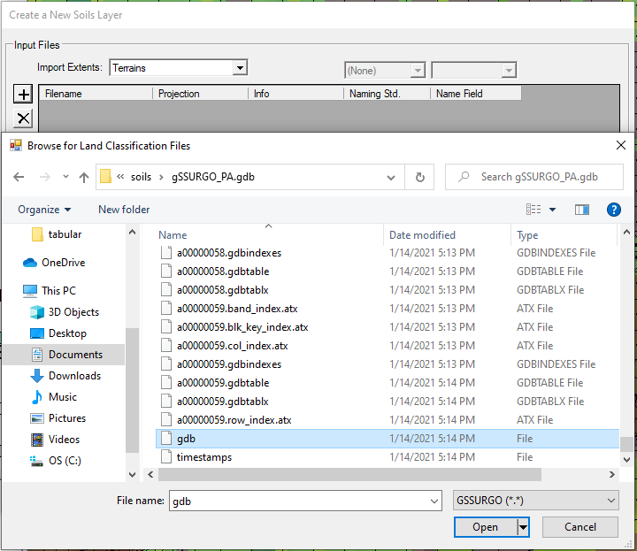
- The downloaded gSSURGO raster file in geodatabase format is in reference to projection of EPSG 5070 (or ESRI 102039, they are the same projection systems) and it can be imported into HEC-RAS directly, letting RAS Mapper handle the re-projection if the HEC-RAS projection system is different from EPSG 5070 (in the demo, the projection system is set as EPSG 26917, UTM Zone 17N, Unit: meter). To create a new soils Layer, go to top menu Project, click Create a New RAS Layer… and then select Soils Layer. Click “+” to add “gdb” file under the geodatabase folder and make sure the file type to open is GSSURGO (Figure 2). Import Extends can be set as Terrains, Geometries, or Entire Input File depending on the project needs.
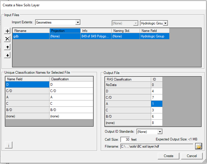
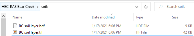
- As shown in Figure 3, RAS Mapper can recognize gSSURGO raster file structure automatically. It should be noted that in Figure 3, the cell size is shown as 30 feet, but it is believed the unit of feet is a display error due to the bug of HEC-RAS 6.0 – the correct unit should be meter since the demo project’s projection system EPSG 26917 has a unit of meter. Two files are created here: a *.hdf file and *.tif file (Figure 4). In this example, since SCS Curve Number method will be used as the infiltration method, the imported gSSURGO raster file needs to be classified by Hydrologic Group and thus the Hydrologic Group will be selected on the top right as shown in Figure 4. If another infiltration method is to be used, for example, Deficit and Constant method, the imported gSSURGO raster file will then need to be classified by soil textures in order to estimate initial deficit, maximum deficit, and percolation rate based on soil textures.
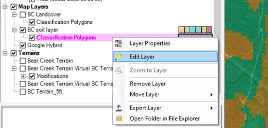
- Optional step: if there is a need to further refine the soils layer, you can add a classification polygon layer under Soils Layer as shown in Figure 5.
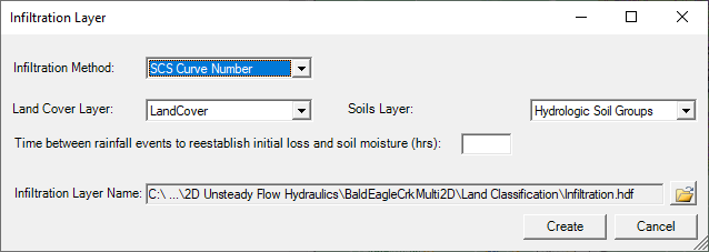
Now an infiltration layer can be created by intersecting the soils layer and the land cover layer.
- To generate a new infiltration layer, go to top menu Project, click Create a New RAS Layer… and then select Infiltration Layer From Land Cover / Soils Layer and pick the soils layer and land cover layer (Figure 6). Select Infiltration Method as SCS Curve Number for this example project.
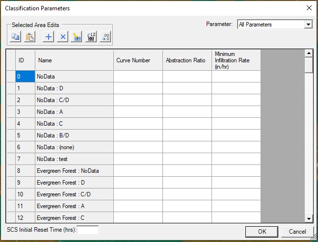
- Right click the newly created infiltration layer and select Edit Infiltration Data to type in appropriate infiltration parameters (Figure 7).
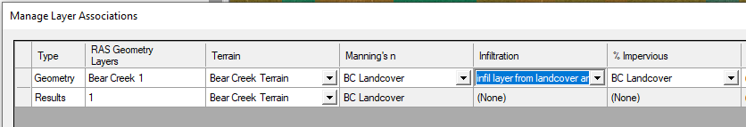
- Finally associate the infiltration layer with the geometry through Manage Layer Associations (Figure 8).
Leave a Reply