Terrain Modification in RAS Mapper (2 of 3)
RAS Mapper of HEC-RAS 6 has a set of terrain modification tools to modify original terrain. This post is the second of the 3 post series for terrain modification using the polygon terrain modification method. Post 1 of 3 focuses on line terrain modification and Post 3 of 3 is for simple shape terrain modification.
It is a good practice to create a virtual clone terrain first and work with terrain modifications on this virtual terrain to keep original terrain untouched. Refer to Post 1 of 3 for virtual clone terrain creation.
The following is a step by step instruction on how to create a detention pond on existing terrain (Virtual Terrain) using polygon feature of terrain modification tools.
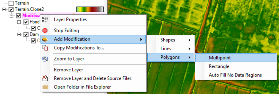
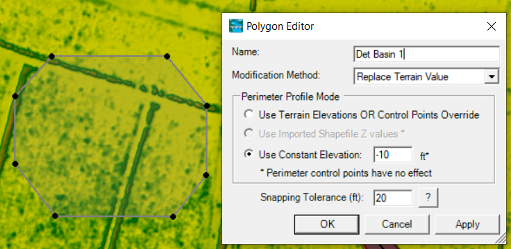
- Right click the Modifications layer to select Add Modification —> Polygons —>Multipoint (Figure 1) to add a multipoint polygon to denote the outside boundary of a detention pond (footprint) by clicking the begin point, and any vertices in between; close the polygon by double clicking the last point. Enter data in the Polygon Editor on Figure 2. In this example, the option of Use Constant Elevation is checked on.
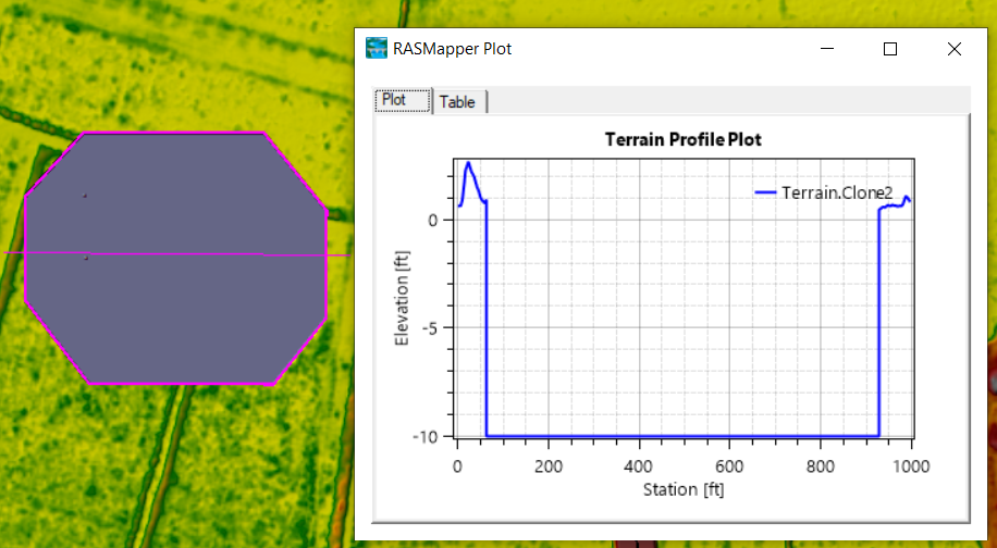
2. The added basin can be reviewed by drawing a profile line across the basin as shown in Figure 2A.
- Elevation control points can be added inside the pond boundary (Multipoint polygon) by using the geometry editing toolbar Add New Feature to define bottom of the pond, when Control Points under Detention Pond is highlighted on Figure 3. Type in a lower elevation when prompted to represent pond bottom.
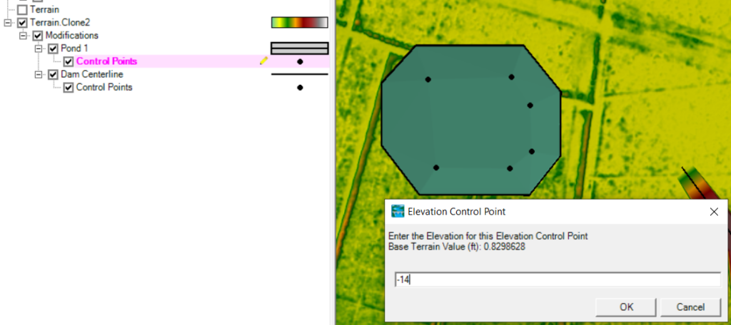
- After adding elevation control points at Step 3, They can be further revised by right clicking Control Points (highlight it in magenta color first) and select Edit Elevation Control Points (Figure 4). In the table of Figure 4, type in the desired elevation and X/Y coordinate values to edit elevation control points and further modify the terrain.

- The cross section view of the basin with the elevation control points is shown in Figure 5.
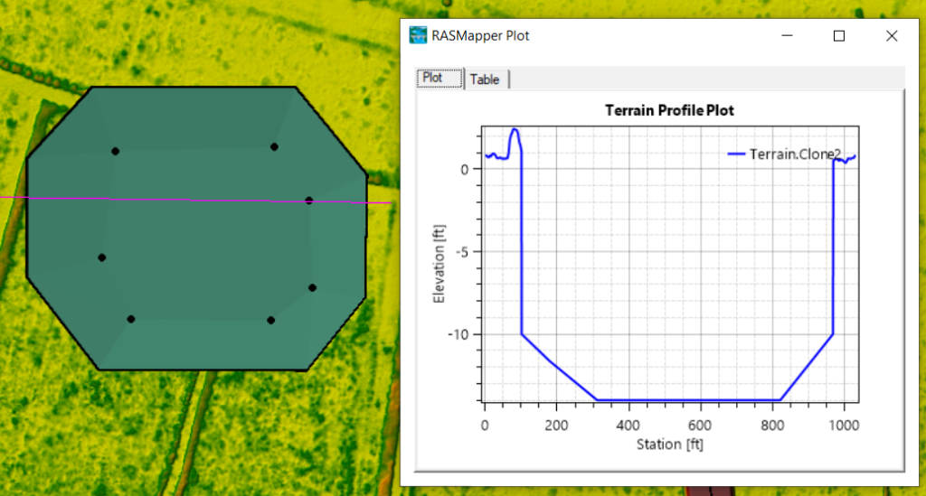
- In lieu of utilizing Elevation Control Points to denote pond bottom, you can also use sets of multipoint polygons to represent the basin inner and outside (Figure 6).
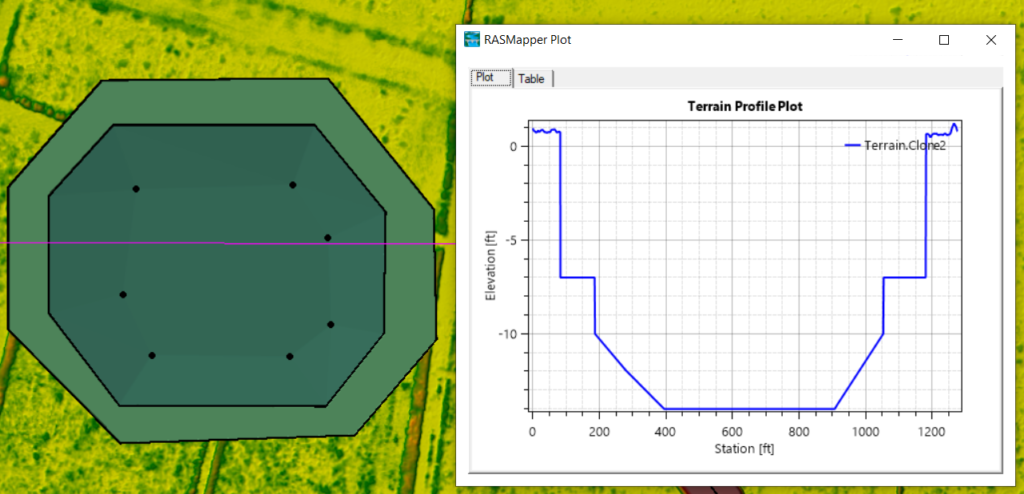
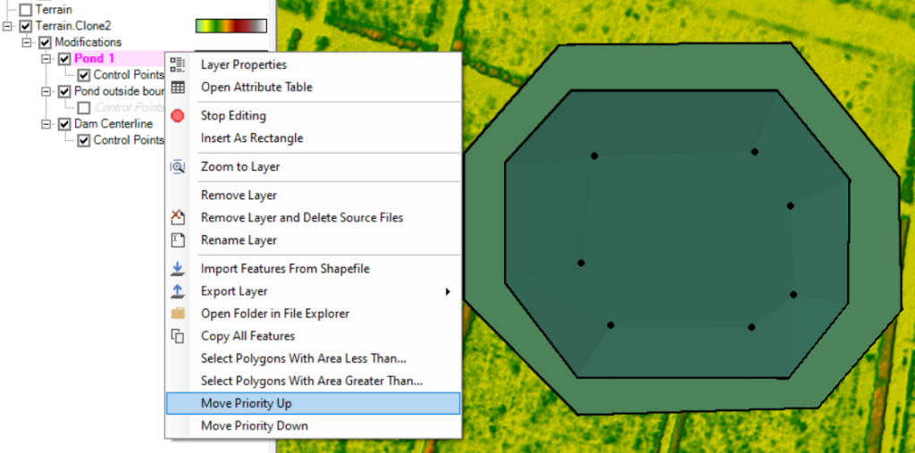
- To achieve the desired results, you may need to adjust the polygons priority by moving them up and and down. In Figure 7, the inner polygon (Pond 1) has the highest priority by moving it up to stay at the top of the list under Modifications layer.
- At the end of editing, make sure to click Stop Editing to save the changes.
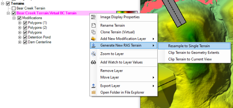
Terrain modifications are implemented as vector additions to the original terrain layer to avoid creating unnecessary extra terrain raster files, however, users have the option to output the modified terrain (original terrain plus modifications) into single terrain by right clicking Terrain —> Generate New RAS Terrain —> Resample to Single Terrain (Figure 8). Three files are to be created by resampling (*.hdf, *.vrt, and *.tif in Figure 9).

Leave a Reply