Terrain Modification in RAS Mapper (1 of 3)
RAS Mapper of HEC-RAS 6 has a set of terrain modification tools to modify original terrain. Basically the terrain modification tools creates vectors (lines/simple shapes/polygons) with elevations assigned to them to revise original terrains. Additionally, Elevation Control Points can be added to further refine original terrains when working together with lines/simple shapes/polygons. Terrain modifications are implemented as vector additions to the original terrain layer to avoid creating unnecessary extra terrain raster files. Vectors for terrain modifications are created and edited using the standard vector editing tools or imported from external shapefiles. Refer to this post for some common GIS operation in RAS Mapper.
This post is the first of the 3 post series for terrain modification introduction with focus on line terrain modification. Post 2 of 3 is to focus on polygon terrain modification and Post 3 of 3 is for simple shape terrain modification.
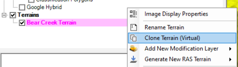
It is a good practice to create a virtual clone terrain first and work with terrain modifications on this virtual terrain to keep original terrain untouched. Select and highlight the original terrain, right click and select Clone Terrain (Virtual) to create a clone of the original terrain (Figure 1).
The following is a step by step instruction on how to create a dam on top of existing terrain (Virtual Terrain) using Line feature of terrain modification tools. A cross section (XS) will be defined under this method and the terrain will be modified based on surface created from the cross section running along the Line feature (Profile), in a way similar to roadway cross section running along roadway center line profile in Open Roads of MicroStation.
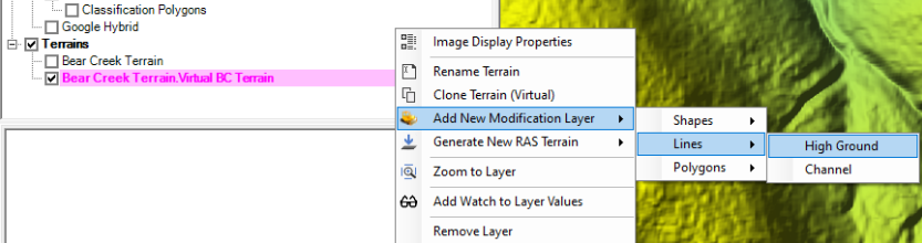
- Right click the virtual terrain to select Add New Modification Layer —> Lines —>High Ground (Figure 2) to add a dam centerline by clicking the begin point, any alignment vertices in between, and the end point.
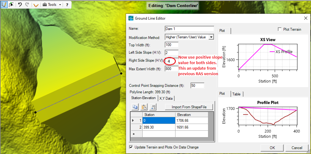
- Edit data in Ground Line Editor (Figure 3). Top width, left side slope and right side slope are used to define a cross section (XS View of Figure 3) running along the line just created. Your are free to edit the Profile station and elevation data table depending on your needs, and the default values are stations and elevations from original terrain – see how the profile line touches original terrain at each end on Profile Plot of Figure 3. The Max Extent Width is the max value of the base width of cross section, if the cross section can not touch (intersect with) original terrain within this Max Extend Width value, the cross section base will not further extend, and instead a vertical wall on each side of cross section will be created to intersect the original terrain. The dam created is shown as the background image on Figure 3.
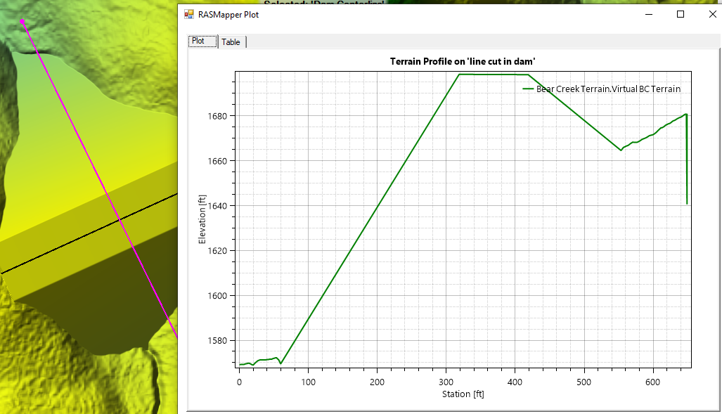
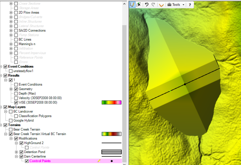
- Another way to review the modified terrain is to draw a profile line in the middle of the dam and then create the profile terrain view (Figure 4).
- In Figure 3, the profile line is a single slope line defined by only two points at begin and end stations. Elevation control points can be added to the profile line if needed by using the geometry editing toolbar Add New Feature to add elevation control points when Control Points under Dam Centerline is highlighted in Figure 5.
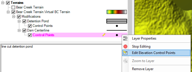
- After adding elevation control points at Step 4, They can be further revised by right clicking Control Points (highlight it in magenta color first) and select Edit Elevation Control Points (Figure 6)
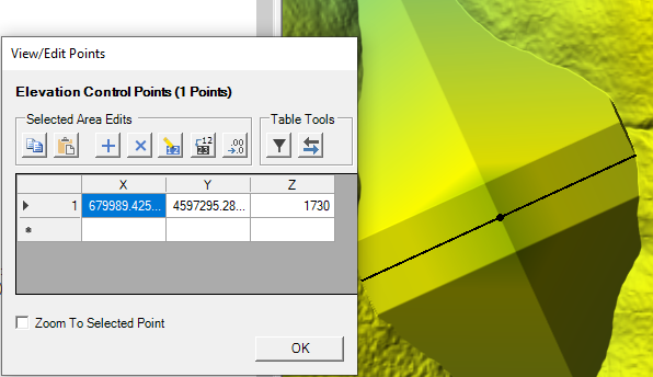
- In the table of Figure 7, type in the desired elevation and X/Y coordinate values to edit elevation control point and further modify the terrain.
- The above steps can be applied similarly to modify terrain by adding a roadway embankment, levee, or any high ground features. To add a channel, choose Channel at Step 1 of Figure 2 instead of High Ground.
- At the end of editing, make sure to click Stop Editing to save all the changes.
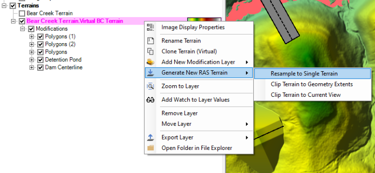
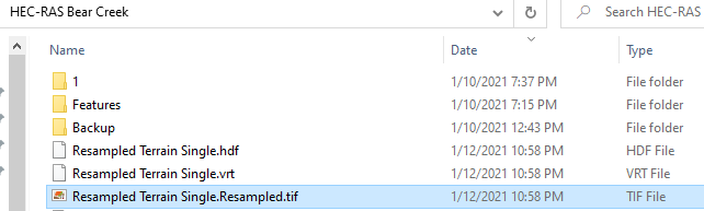
Terrain modifications are implemented as vector additions to the original terrain layer to avoid creating unnecessary extra terrain raster files, however, users have the option to output the modified terrain (original terrain plus modifications) into single terrain by right clicking Terrain —> Generate New RAS Terrain —> Resample to Single Terrain (Figure 8). Three files are to be created by resampling (*.hdf, *.vrt, and *.tif in Figure 9).
Leave a Reply