Use HEC-RAS to Develop Storage-Discharge Paired Data for Modified Puls Routing in HEC-HMS
Modified Puls Routing, also known as storage routing or level-pool routing, is a commonly used reach (channel) routing method in HEC-HMS. Modified Puls Routing is based on continuity equation. In Equation 1, only St (storage) and Ot (outflow or discharge) at time step t are unknown, and to solve it a relationship between storage and discharge must be supplied to reduce Equation 1 to a nonlinear equation with only only unknown Ot. It is worth noting that the underlying assumption here is that storage depends primarily, if not solely, on outflow. Modified Puls routing was originally developed for reservoir routing where a unique storage-outflow is likely. When applying Modified Puls routing method to a channel, some routing errors will be introduced inevitably since storage in a river reach usually is not a function of outflow alone.

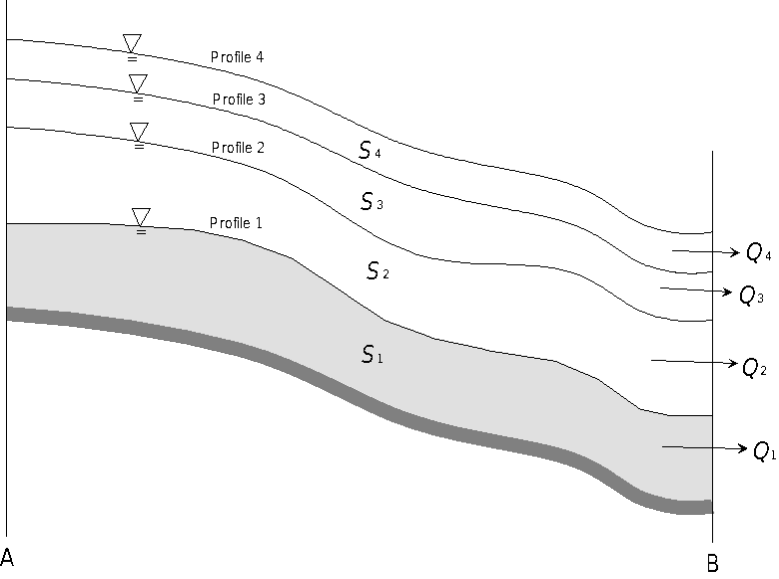
Historical river stage and flow records can be used to develop the relationship between storage and discharge (outflow), but they are usually not available for most engineering applications. Alternatively, water surface profiles (thus storages) can be computed for a range of discharges with HEC-RAS under steady-state modeling to develop the required relationship as illustrated in Figure 1. After successful steady-state HEC-RAS multi-profile run, the paired data starting with 0: 0 including S1: Q1, S2:Q2, S3: Q3,… can be typed in to HEC-HMS to define a storage-discharge function for Reach A-B.
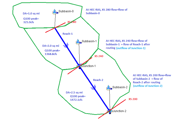
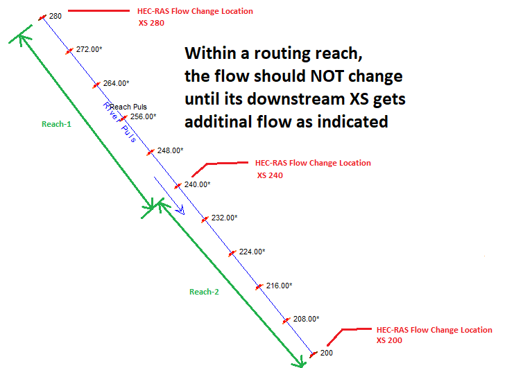
The steps to create storage-discharge paired data (curve) are explained in details in HCFCD Hydrology and Hydraulics Manual. A HEC-HMS model (download initial HMS model in zip here) has been set up and its hydrologic element layout is shown in Figure 2. Reach-1 and Reach-2 in Figure 2 are to be routed by Modified Puls Routing method and they are modeled in HEC-RAS (download initial RAS model in zip here) by steady state modeling (Figure 3). However, at the beginning since their storage-discharge relationships are unknown, to get an initial values for XS 240 and XS 200 in HEC-RAS (outflows of Junction-1 and Junction-2), both reaches are assigned to apply Lag routing method for the first HEC-HMS run.
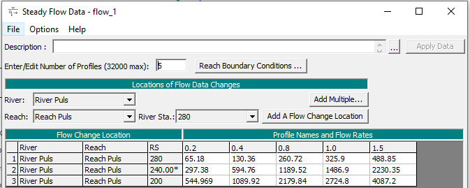
A range of flows are needed to run the multi-profile steady-state HEC-RAS model and the expected maximum peak flows from HMS modeling should be covered by the selected flow ranges. For this example project, the base flow uses Q100 peak flows (profile 1.0) calculated from HEC-HMS and other flows are 0.2*Q100 peak flows (profile 0.2), 0.4*Q100 peak flows (profile 0.4), 0.8*Q100 peak flows (profile 0.8), 1.5*Q100 peak flows (profile 1.5), The flows for XS 240 and XS 200 are outflows of Junction-1 and Junction-2 respectively and their initial values are from first HEC-HMS run by using Lag routing method for Reach-1 and Reach-2 since the storage-discharge relationships are not known yet (Figure 4).
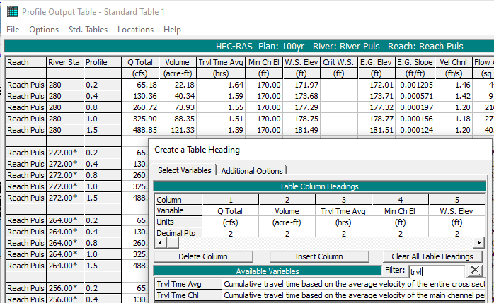
After initial flows for multi-profile HEC-RAS steady flow model are established, run the model and open Ouput Summary Table (Standard Table 1) to show the results for each cross section . Open Options—>Define Table… to add two variables – Volume (acre-ft) and Trvl Time Ave (hrs) to the table column (Figure 5). The Volume variable is the cumulative volume of water under each profile from the very downstream end cross section to the current cross section and Trvl Time Avg is the travel time based on the average velocity of the entire cross section.
Summarize the above Standard Table 1 as shown in Figure 6 to develop the storage-discharge relationships (paired data) for Reach-1 (XS 280 to XS 240) and Reach-2 (XS 240 to XS 200). Trvl Time from Upstream XS to Downstream XS is used to calculate number of subreaches for Modified Puls routing method. According to HEC-HMS Technical Reference Manual and HCFCD Hydrology & Hydraulics Manual, by assuming flood wave velocity is 1.5 times as much as water travel velocity, the number of subreaches can be estimated as follows:
- Flood Wave Travel Time=Trvl Time from Upstream XS to Downstream XS/1.5;
- Number of subreaches=Flood Wave Travel Time/HEC-HMS Time Step (Time Interval).
In this example project, the HEC-HMS time interval is 10 minutes and the numbers of subreaches are calculated as 5 and 2 respectively for Reach-1 and Reach-2. (Note: The number of subreaches impacts the attenuation of the calculated hydrograph in HEC-HMS and it can be used as a calibration parameter if gaged flow data is available)
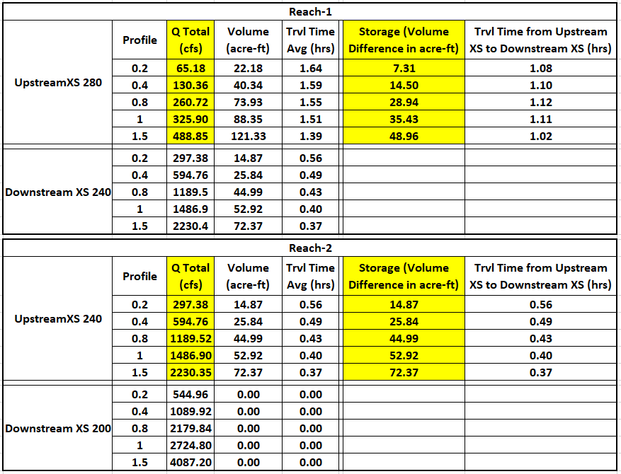
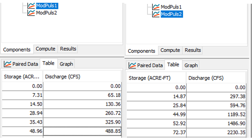
Type in the highlighted storage-discharge data points in Figure 6 starting from 0:0 for Reach-1 and Reach-2 in HEC-HMS (Figure 7). Change Reach-1 and Reach-2 routing method to Modified Puls and re-run the HEC-HMS model to get another set of peak flows for Junction-1 and Junction-2.
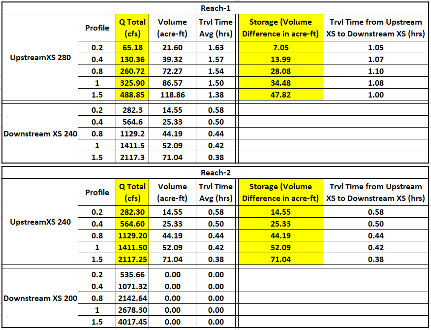
Update HEC-RAS model steady flow data by these new peak flows from HEC-HMS and repeat the above steps to re-run the HEC-RAS model to get new Volume (acre-ft) and Trvl Time Avg (hrs). Use the updated Volume and Trvl Time Avg to re-calculate the storage-discharge paired data and numbers of subreaches (Figure 8 and Figure 9).
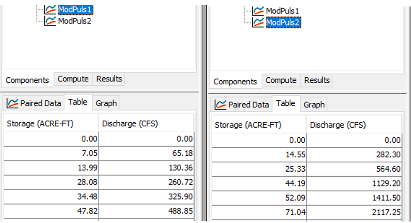
Repeat the above step to re-run HEC-HMS and HEC-RAS models until the calculated peak flows of Junction-1 and Junction-2 are converging to certain values (The differences between two consecutive runs are less than 5%, for example). Use the most up-to-date storage-discharge paired data as your final results.
In the example project, in the third HEC-HMS run (using storage-discharge paired data in Figure 9), the calculated peak flows of Junction-1 and Junction-2 are 1413.3 cfs and 2675.4 cfs, very close to the values of the 2nd HEC-HMS run 1411.50 cfs and 2678.30 cfs (using storage-discharge paired data in Figure 7), the HEC-HMS and HEC-RAS cycling (balancing) process can stop and the final storage-discharge paired data is shown in Figure 9. To download the final versions of HEC-HMS and HEC-RAS models of this example project, click here and here.
Leave a Reply