Conduit US and DS Headloss (Entrance Loss and Exit Loss) in InfoWorks
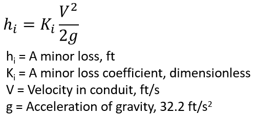
Head Losses (or energy losses) associated with conduits in a storm sewer system include pipe friction losses and minor losses. Pipe friction losses are normally solved by Manning’s equation, while a minor loss is calculated as the product of a minor loss coefficient and the velocity head (Figure 1). There are different kinds of minor losses, such as entrance loss, exit loss, bend loss, and pipe size transition loss, and the total minor loss for a conduit is the sum of all of the applicable minor losses.
To correctly calculate HGL in a storm sewer design project, the minor losses must be accounted for and FHWA HEC-22 has a whole chapter (Chapter 7) to explain the procedures. For a modeling type project, some slack can usually be cut when dealing with minor losses, particularly for long pipes where the pipe friction losses would dominate. A 2006 paper authored by W. H. Frost stated that in long conduits (Length/Diameter >> 1000) the minor losses are usually very small and can be neglected.
It is still beneficial for a H&H modeler to understand and set up minor losses appropriately when they can not be ignored completely. Comparing to EPA SWMM and XPSWMM, InfoWorks has different methods to calculate US and DS headloss and this post is to focus on pipe entrance and exit losses at a manhole by “Normal” loss type in InfoWorks (a default conduit setting). Other loss types will only be briefly discussed at the end. The “Normal” loss type is widely accepted due to its simplicity and the fact that InfoWorks built-in “Inference” function can populate its headloss coefficients (Ku, user defined headloss factor) automatically. Both City of Winnipeg and Toronto InfoWorks modeling guidelines recommend “Normal” as the default US and DS headloss type.
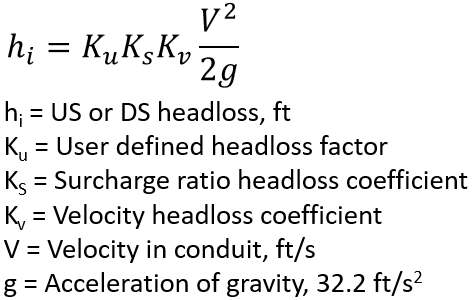
InfoWorks evaluates the minor loss coefficient as 3 components and each of the coefficients (factor) is handled differently. Of the 3 coefficients (Figure 2), surcharge ratio headloss coefficient Ks plays a major role in calculating headloss while the user defined headloss factor and velocity headloss coefficient are meant to adjust Ks due to different flow approaching angles and directions (entering or exiting a conduit). Only user defined headloss factors need to be provided by modelers in InfoWorks.
- Surcharge ratio headloss coefficient Ks
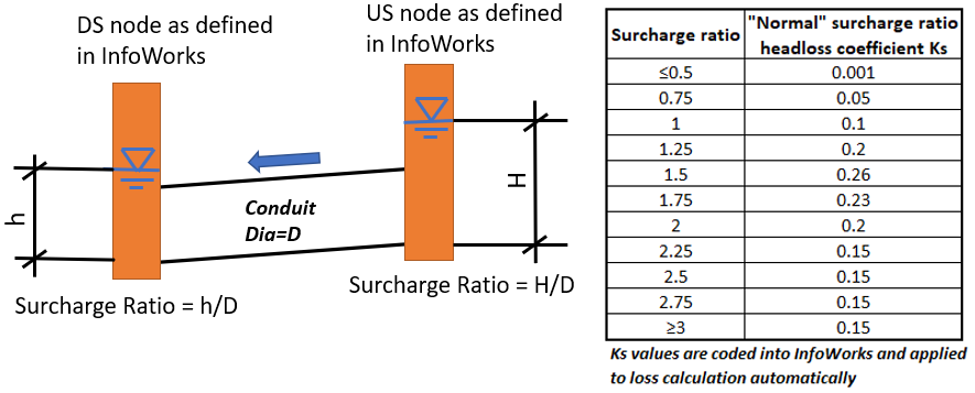
Surcharge ratio headloss coefficient Ks defines the relationship of headloss and surcharge ratio (Figure 3). It is the major one of the 3 coefficients used by InfoWorks for “Normal” loss type. There is negligible headloss from surcharging for conduits flowing less than half full and only small headloss up pipe full. The surcharge headloss is 0.15 times the velocity head for large depths of surcharge. Modelers do not need to enter a Ks value, and instead InfoWorks will apply correct Ks based on the Table in Figure 3 for “Normal” loss type.
- Velocity headloss coefficient Kv
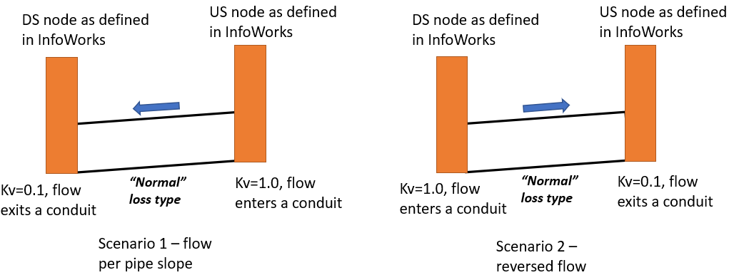
It is generally agreed that the flow is more turbulent when it enters a pipe from a manhole (thus more losses) than when it exits pipe to discharge to a manhole. For this reason, InfoWorks “Normal” loss type introduced a velocity headloss coefficient Kv, which is equal to 1.0 for flow entering a pipe but will be 0.1 for flow exiting a pipe to discharge to a manhole. The Kv is coded in InfoWorks and the value (0.1, 1, and a short linear interpolation between them) is applied to loss calculation automatically based on flow entering or exiting a pipe. It is worth noting that Kv value, 1.0 or 0.1, is not chosen based on a conduit US or DS node assignment (Figure 4).
- User defined headloss factor Ku
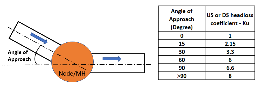
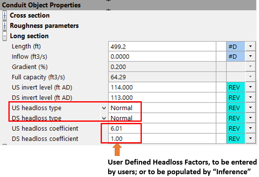
User defined headloss factor Ku is to represent the headloss from the change of flow direction when a conduit enters a manhole at a different direction from the exiting conduit. Modelers are to enter the Ku values as shown in the table of Figure 5 based on angle of approach (Figure 6).
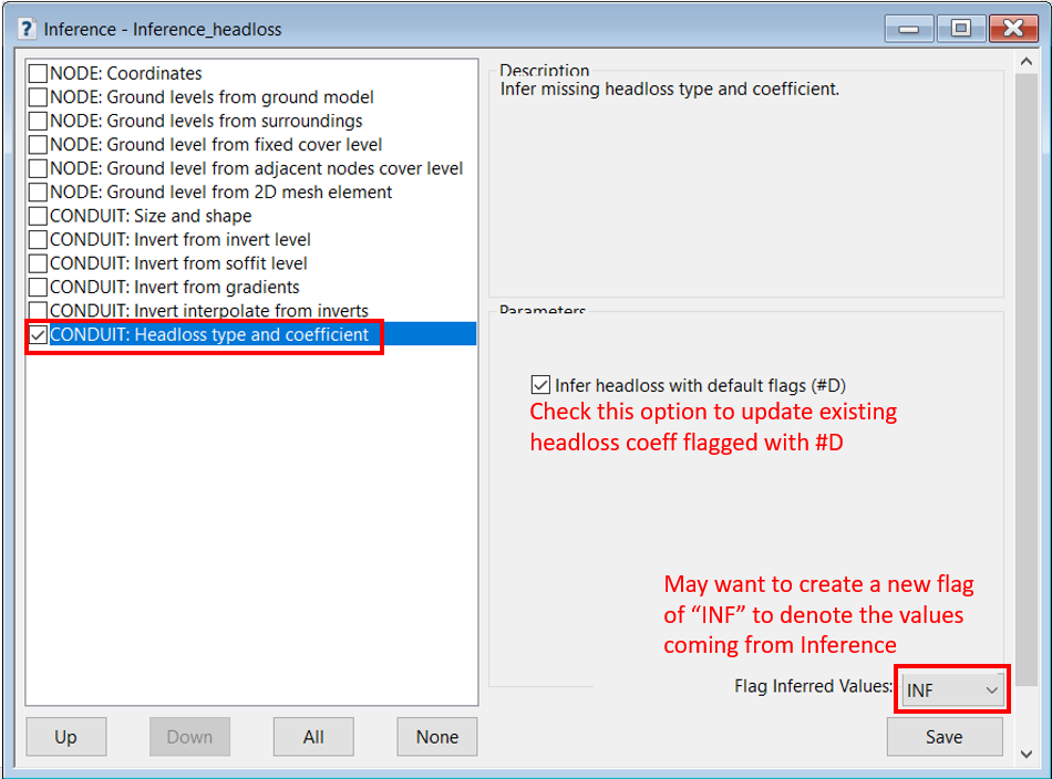
Alternatively, the InfoWorks built-in “Inference” function can be used to infer headloss coefficients automatically (Ku, user defined headloss factor) based on the storm sewer network layout angles (Figure 7). This headloss coefficient “Inference” function only works for “Normal” loss type and more details about its functionality can be found from InfoWorks online help documents.
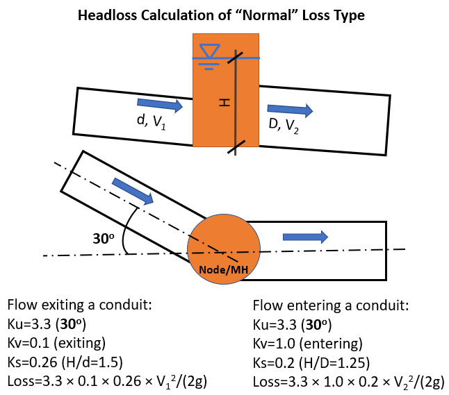
An example headloss calculation is illustrated in Figure 8 which uses “Normal” loss type.
There are other types of headloss in InfoWorks in addition to “Normal” loss type for conduits. The “None” type means the program will not calculate headloss at US or DS end of a conduit. The “FHWA” type is to apply the loss method described in FHWA HEC-22 Section 7.1.6.7 FHWA Inlet and Access Hole Energy Loss (for more details refer to this post or this example problem). The other two headloss types are explained below with the focus on the differences from “Normal” loss type.
- “High” loss type
The “High” loss type is very similar to “Normal” loss except that the it usually employs a larger surcharge ratio loss coefficient which makes it suitable for poorly constructed manholes that are only benched to half pipe height. The built-in headloss coefficient “Inference” function does not work for this loss type.
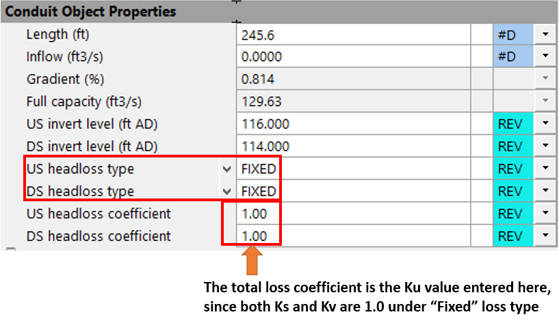
- “Fixed” loss type
In the “Fixed” loss type, the surcharge ratio loss coefficient Ks and velocity coefficient Kv are always to be set as 1.0, no matter flow enters or exits a pipe. Therefore, the only factor matters is the user defined headloss coefficient Ku which is to be supplied in the conduit property editor (Figure 9). The built-in headloss coefficient “Inference” function does not work for this loss type either. A modeler needs to think about using other US/DS headloss coefficients such as 1.0/0.5, 1.0/0.1, or even 0.5/0.5, 0.5/0.1, if they make sense to your specific conditions, instead of always sticking with 1.00 and 1.00.
- “User Defined” loss type
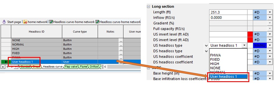
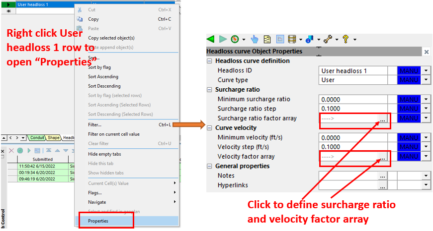
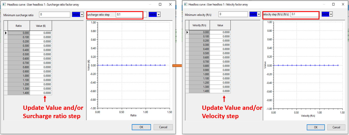
“User Define” loss type allows a modeler to specify the surcharge ratio loss coefficient Ks and velocity coefficient Kv in a tabular format. To enable this loss type method, first open the link grid window and enter a user defined loss type name (Figure 10); right click it to open its properties window (Figure 11). Two tables are needed to define Ks and Kv (Figure 12). Last, the modeler needs to select the user defined loss type name and provide Ku for US headloss coefficient and DS headloss coefficient in the conduit property editor window (Figure 10).
Leave a Reply