Pipe Entrance Loss And Exit Loss Coefficients In A Manhole For Modeling
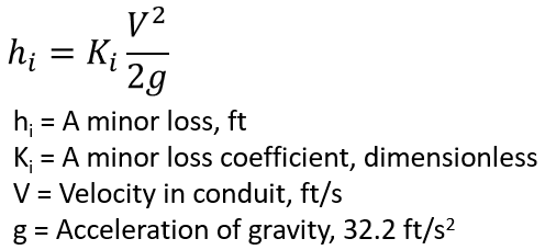
Head Losses (or energy losses) associated with conduits in a storm sewer system include pipe friction losses and minor losses. Pipe friction losses are normally solved by Manning’s equation, while a minor loss is calculated as the product of a minor loss coefficient and the velocity head (Figure 1). There are different kinds of minor losses, such as entrance loss, exit loss, bend loss, and pipe size transition loss, and the total minor loss for a conduit is the sum of all of the applicable minor losses.
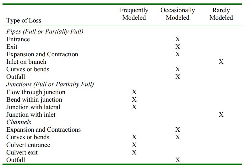
Minor losses are usually accounted for differently in design and modeling projects: for design, every single loss probably needs to be calculated to get a correct HGL; on the other hand, for a modeling project, a modeler tends to focus on critical components depending on the overall modeling goal and pay less attention to minor or too detailed elements (example: inlets, laterals, or small branches) by truncating or lumping them into runoff process. For this reason, W. H. Frost stated in a 2006 paper that minor losses including entrance and exit losses are often ignored in a storm sewer system model (Table 1), especially when Pipe Length/Diameter >> 1000. Mr. Frost further summarized how different types of minor losses are calculated under various flow conditions and recommended typical loss coefficient values and methods in Table 23.21 of the 2006 paper.
HEC-22 Section 7.1.6.7 FHWA Inlet and Access Hole Energy Loss is the most suitable and accurate method to calculate the losses across a manhole, and it supersedes the previous FHWA Corrective Coefficient Energy Loss Method and Composite Energy Loss Method.
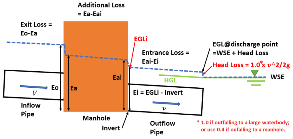
According to HEC-22, the FHWA Inlet and Access Hole Energy Loss Method employs hydraulically sound equations for loss computations under inlet control and full flow conditions. As illustrated in Figure 2, the total loss in a manhole can be grouped into three components and each component is to be calculated separately.
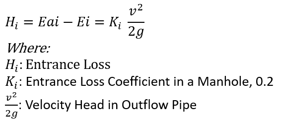
Under full or partially full subcritical flow control condition, The entrance loss Eai-Ei can be calculated by the equation in Figure 3. HEC-22 suggest using the concept of Discharge Intensity (DI) to calculate Eai if a pipe is under inlet control (submerged or unsubmerged). It is impossible to enter a head loss not expressed as a function of velocity heads in EPA SWMM and XPSWMM, so this post does not consider the inlet control condition for the entrance loss. InfoWorks ICM fully implements the entrance loss method under inlet control and an example can be found here. The interested readers can also refer to HEC-22 Equation 7-17, 7-18 and 7-19 on Page 7-20.
The additional loss in a manhole consists of three components as explained by equations in Figure 4.
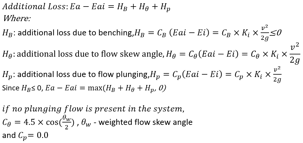
The benching loss coefficient CB is listed in HEC-22 Table 7-6 and the calculation of the skew angle loss coefficient and the plunging flow loss coefficient is explained on HEC-22 Page 7-22 through 7-24. If the manhole to be evaluated is also an inlet, the inlet inflow is considered as a plunging flow which may impact the flow skew angle and its loss coefficient calculation (the manhole’s non-plunging inflow and the total outflow ratio is not 1.0). If the calculated additional loss is a negative value (it is possible since CB is negative sometimes), set it as 0.0.
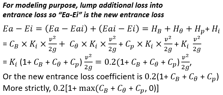
In some storm water modeling tools such as EPA SWMM or XPSWMM, there is no place to enter additional loss parameters and therefore they are often combined with the entrance loss introduced above to create a “new” type of entrance loss coefficient (Figure 5).
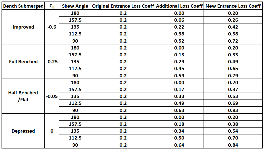
The “new” combined entrance loss coefficients of an outflow pipe for a simple pipe and manhole configuration (Figure 6) without plunging flows are computed and summarized in Table 2. Some models use 0.5 as the entrance loss coefficient blindly everywhere, and this practice may have actually overestimated the losses if considering the fact that in a typical storm sewer network, most of the pipes are in a straight alignment, and the alignment deflection or connection with other trunk lines only happens at a few locations along the entire length. VDOT Drainage Manual Chapter 9 suggests using 0.35 as the entrance loss coefficient, which may be a more reasonable average value if using 0.20 everywhere is not conservative enough.

The inflow pipe exit loss in a manhole is calculated by the equation in Figure 7.

It should be noted that the exit loss coefficient of 0.4 in Figure 7 is for a pipe discharging to a manhole. If it outfalls to a large waterbody such as a lake or a reservoir where the velocity is reduced to near zero, the exit loss coefficient should be assumed to be 1.0 since in this scenario the entire velocity head of the discharge pipe is dissipated (Figure 2).
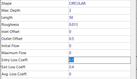
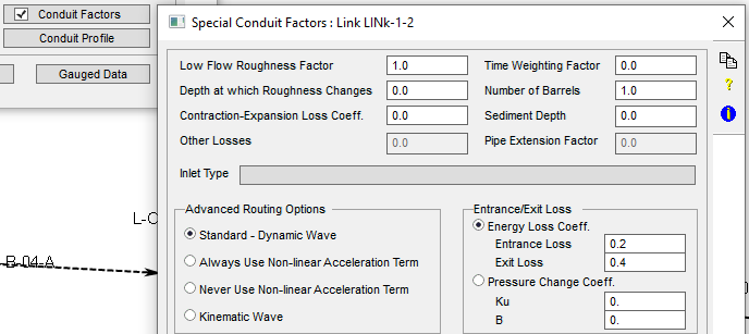
In EPA SWMM and XPSWMM, entrance and exit loss coefficients are entered in link/conduit properties windows (Figure 8 and Figure 9). Infoworks handles the entrance and exit loss coefficients differently, and the detail can be found here.
Since only the continuity equation is solved in a manhole (node) in EPA SWMM and XPSWMM, minor losses have to be included in the conduit’s St. Venant momentum equation by treating them as a loss per unit length, hL, in the same way that the friction slope Sf is treated per EPA SWMM Hydraulics Reference Manual (Figure 10).
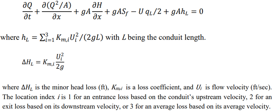
For this reason, including minor losses in a conduit’s St. Venant momentum equation is like an increase in the conduit’s Manning’s n. In fact, in this discussion, Mr. Reinhard Sprenger suggested adjusting Manning’s n to account for minor losses: I haven’t been using the entrance and exit coefficients feature at all in any of my studies. Instead I’ve been estimating these losses and ensuring that they are covered within the friction losses by cooking Manning’s roughness. He further recommended a Manning’s n of 0.013 for a concrete conduit which is able to cover various minor losses for most cases: since every report or study I’ve ever seen uses 0.013, or something close, I figure I can use the same value that everyone expects to see and also feel comfortable that I am considering miscellaneous losses as well. If I used 0.013 for a friction factor and added the entrance and exit loss coefficients it would amount to including the manhole losses twice. Of course, the above are Mr. Reinhard Sprenger’s personal opinions, and it is always up to each individual modeler on whether or not to account for pipe entrance and exit losses in a storm water system model and how.
Based on the above discussions, it seems the pipe entrance loss and exit loss coefficient calculation is not a settled issue, especially for a modeling project where its flow regimes often changes (design is a different story in which only a constant peak flow value is considered). More future researches about this topic are warranted for academic world and regulating agencies and meanwhile, as a modeler, the following can be considered when selecting appropriate entrance and exit loss coefficients:
- Always refer to the project regulating agency’s drainage design or H&H manual for entrance and exit loss coefficient requirements;
- Ignore entrance and exit losses in a model. In fact, it appears that this is the default method for a lot of EPA SWMM and XPSWMM models in today’s engineering world. When ignoring entrance and exit losses, it is better to use a Manning’s n of 0.013 for concrete pipes. Note that King and Brater recommended the corresponding Manning’s n range as 0.011 to 0.012 for design in Handbook of Hydraulics (1963), so using a value of 0.013 may be able to account for the ignored minor losses to some degree;
- Use HEC-22 Section 7.1.6.7 FHWA Inlet and Access Hole Energy Loss Method to calculate entrance loss coefficients as introduced above. Table 2 lists some typical “combined” entrance loss coefficient values for a simple pipe and manhole configuration without considering plunging flows, which can be used as input to EPA SWMM or XPSWMM models. Only InfoWorks has fully implemented FHWA Inlet and Access Hole Energy Loss Method.
- HEC-22 Section 7.1.6.7 FHWA Inlet and Access Hole Energy Loss Method suggests the pipe exit loss coefficient in a manhole is 0.4, however, when a pipe discharges to a large waterbody, the exit loss coefficient is usually 1.0.
- Refer to Table 23.21 of the 2006 paper by W. H. Frost for some recommended loss coefficient values.
- It is probably not appropriate to use culvert entrance loss coefficients in Table C.2, Appendix C of HDS-5 for storm sewer pipes connecting to a manhole unless you really want to model them as culverts.
- Entrance and exit loss coefficients should be 0.0 in a dummy node to break up a single long conduit into shorter segments.
Leave a Reply