Design A Detention Basin Using SCS Hydrology in HydroCAD
A previous post introduced the design of a detention basin using Modified Rational Method in HydroCAD, and this post is about detention basin design using SCS hydrology in HydroCAD. The two methods share the same basic principles regarding the required detention basin volume determination, sizing, and outflow control structure modeling.
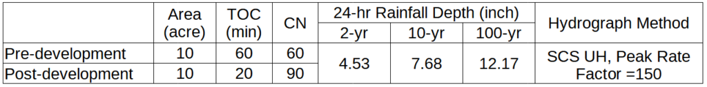
The example is a commercial development project of 10 acres located in Austin County, TX. Its pre-development and post-development site conditions and peak flows are summarized in Table 1. The local storm water regulation requires a detention basin to be designed for a 100-yr storm and control outflows from 2-yr, 10-yr, and 100-yr storm events so the post-development peak flows are no greater than the corresponding pre-development values. The example project uses the SCS hydrology (CN for loss and SCS Unit Hydrograph for transform) in HydroCAD to develop the required pre- and post-development hydrographs.
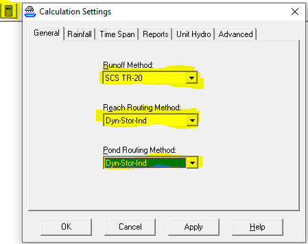
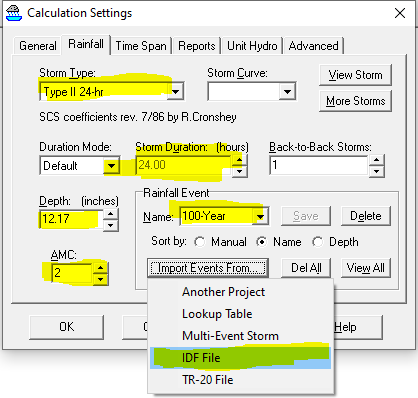
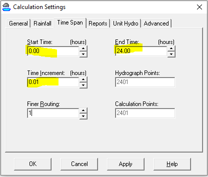
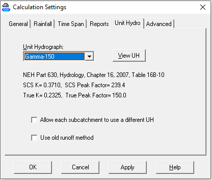
To establish a new model in HydroCAD, first click Project–>Open… and enter a new project name to create a new project. Now open the HydroCAD Calculation Settings window by clicking the calculator icon to set up the runoff method (SCS TR-20) and reach/pond routing method (Figure 1). Under the “Rainfall” tab (Figure 2) set up storm type (rainfall temporal distribution), storm duration (normally 24-hr, unless the watershed is very vey big with TOC>24hr), AMC =2 (normal Antecedent Moisture Condition), and import events from IDF File to acquire 24-hr rainfall depths of various return-period storms. Make sure the start time is 0.00 and the end time is 24.00 (can be longer, for example 48) under “Time Span” tab in Figure 3. The depth value can also be typed in directly, and then give it a name to save it. In “Unit Hydro” tab, choose SCS UH with Gamma-150 since the project area is flat and a peak rate factor less than the standard value of 484 is warranted.
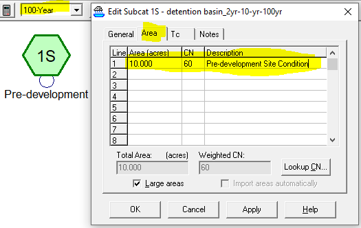
To develop a pre-development site hydrograph in HydroCAD, drag the green color “Subcat” creation icon to the main window blank area. Right click the “1S” subcatchment to open its data editor window (Figure 5). Rename the “1S” subcatchment as “Pre-development” and enter its area, Curve Number, and TOC per the values in Table 1 under each of the tabs – General, Area, and Tc. Click “OK” to close its data editor window.
Similar to the step above, now add a new subcatchment “2S” named Post-development to get the inflow hydrograph for the detention basin. Enter “2S” subcatchment area, Curve Number, and TOC per the values in Table 1 for post-development.
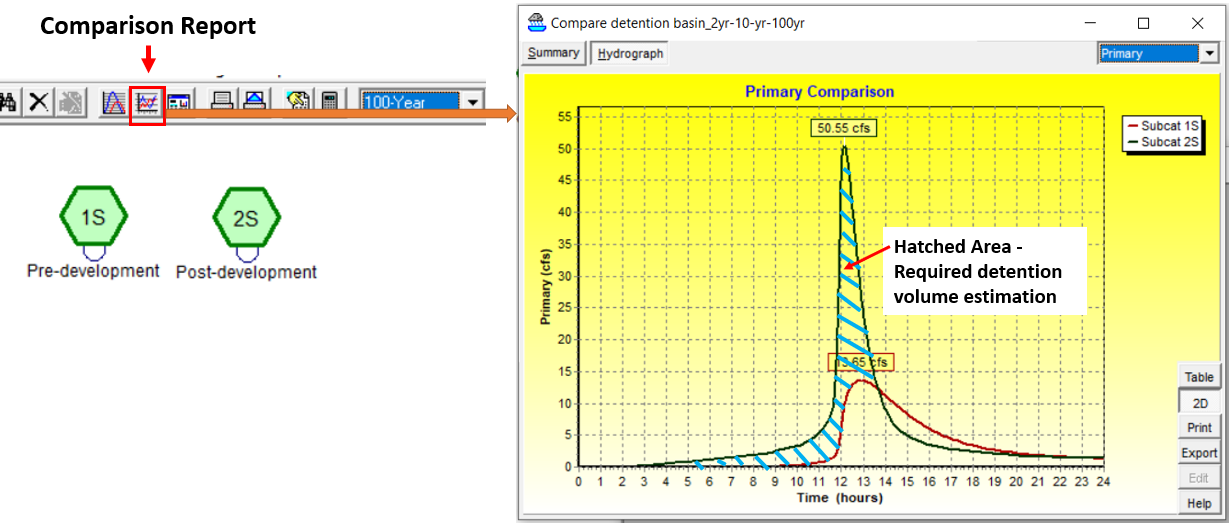
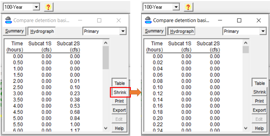
Use Ctrl + mouse to select both 1S and 2S subcatchments and the click Comparison Report Icon to view their hydrographs/time series tables within a single window under 100-yr storm event. The preliminary required detention volume can be estimated as the hatched area in Figure 6. Click the “Table” button or “Hydrograph” tab of Figure 6 to view the time series. If more points need to be listed in the table, click the “Shrink” button in Figure 7. The table in Figure 7 can be exported as a CSV file by clicking the “Export” button and the hatched area (required volume) can be easily calculated in MS Excel. The required volume for this example project is 201273.5 cu ft or 4.621 ac-ft to detain 100-yr storm runoff.
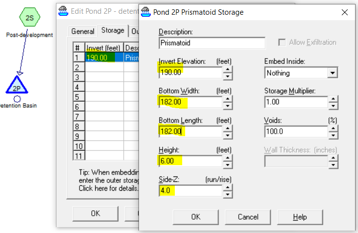
Drag the triangle icon of pond to the main HydoCAD window to add a detention basin to the model and renumber it as “2P“. Connect “2S” subcatchment to “2P” pond (Figure 7). Assume the proposed detention basin is to be 6.0ft deep including 1.0ft freeboard and its bottom is at elevation 190.00ft. The required detention basin bottom (square shape) side length is about 182.0ft to provide 201273.5 cu ft volume from elevation 190.0ft to 195.0ft. For preliminary design purpose, the detention basin can take the shape of a prismatoid and its storage relationship can be defined as such (Figure 7). You may also use “custom stage data” to define the detention basin if that’s what you prefer.
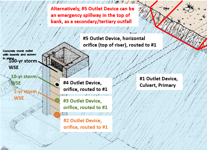
In this example, the proposed outflow control structure is a group of culvert, orifices and weir as shown in Figure 8. The design purpose is to regulate storm water discharges from the detention basin under 2-yr, 10-yr, and 100-yr storm events separately as required by the local codes.
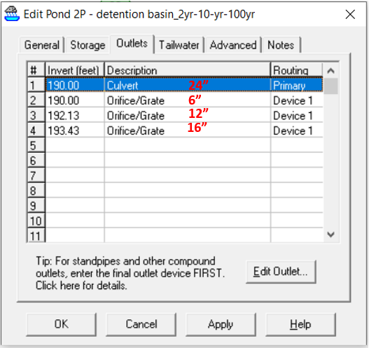
Follow the steps in this post, which is an iterative process to adjust outlet device elevations and sizes, and even the detention basin storage volume and dimensions, the final results are shown in Figure 9 with outlet device configurations shown in Figure 10. During the model iteration runs, the detention basin bottom dimension was increased to 190 ft x 190 ft from the original size of 182 ft x 182 ft. The peak stage elevation under 100-yr storm is 194.87ft, which meets the minimum 1.0ft freeboard requirement.
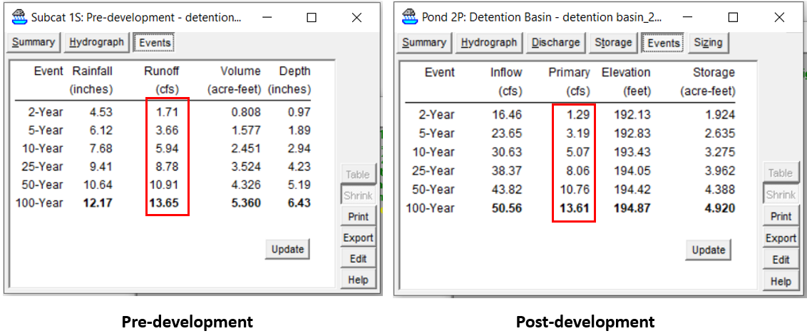
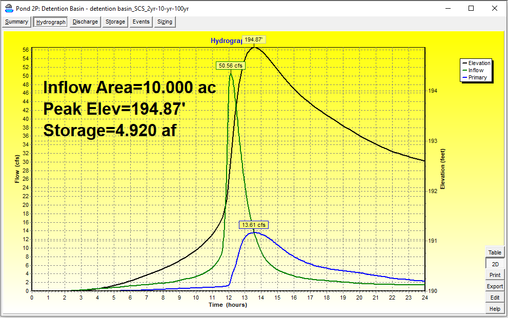
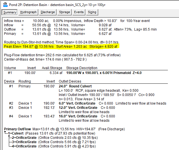
The final inflow and outflow hydrographs of the proposed detention basin is shown in Figure 11 and the summary report is in Figure 12. The final storage at 100-yr peak stage elevation of 194.87ft is 4.920 ac-ft which is slightly greater than the preliminary volume of 4.621 ac-ft.
The modeling of #5 outlet device in Figure 8 was not perform for this example project, but if interested in the steps, refer to the post here.
The finished model file can be downloaded here.
Leave a Reply